
Method and system for the ply-by-ply machining of a component made of composite material, by applying energy

a composite material and machining technology, applied in the field of plybyply machining of composite material components, can solve the problems of difficult to adapt the recesses of manual machining to the above singularities, high time consumption, and variations in the geometry of components before, during and after, and achieve constant ply machining. , the effect of eliminating defects

Active Publication Date: 2015-04-09
JEDO TECH
View PDF5 Cites 6 Cited by
  • Summary
  • Abstract
  • Description
  • Claims
  • Application Information

AI Technical Summary

Benefits of technology

The invention proposes a way to machine composite components by removing material in a way that is adaptable to the individual parts being machined. It can detect and remove defects or damage automatically, ensuring constant and reproducible machining. The process uses image analysis to identify the defects and adjusts the machining speed accordingly. Luminous flux is also detected and processed with sufficient contrast to make up for any error caused by lighting orientation.

Problems solved by technology

However, this manual machining is difficult to reproduce and is highly time-consuming.
However, it is difficult to adapt these recesses to the aforementioned singularities.
Furthermore, internal stresses in composite materials created in the course of manufacture cause variations in the geometry of a component before, during and after machining.
These variations in geometry make it difficult to use shaping tools, such as conventional machining tools, because they require a precise knowledge of the geometry of the component.

Method used


Image

  • Method and system for the ply-by-ply machining of a component   made of composite material, by applying energy
  • Method and system for the ply-by-ply machining of a component   made of composite material, by applying energy
  • Method and system for the ply-by-ply machining of a component   made of composite material, by applying energy

Examples


Embodiment Construction

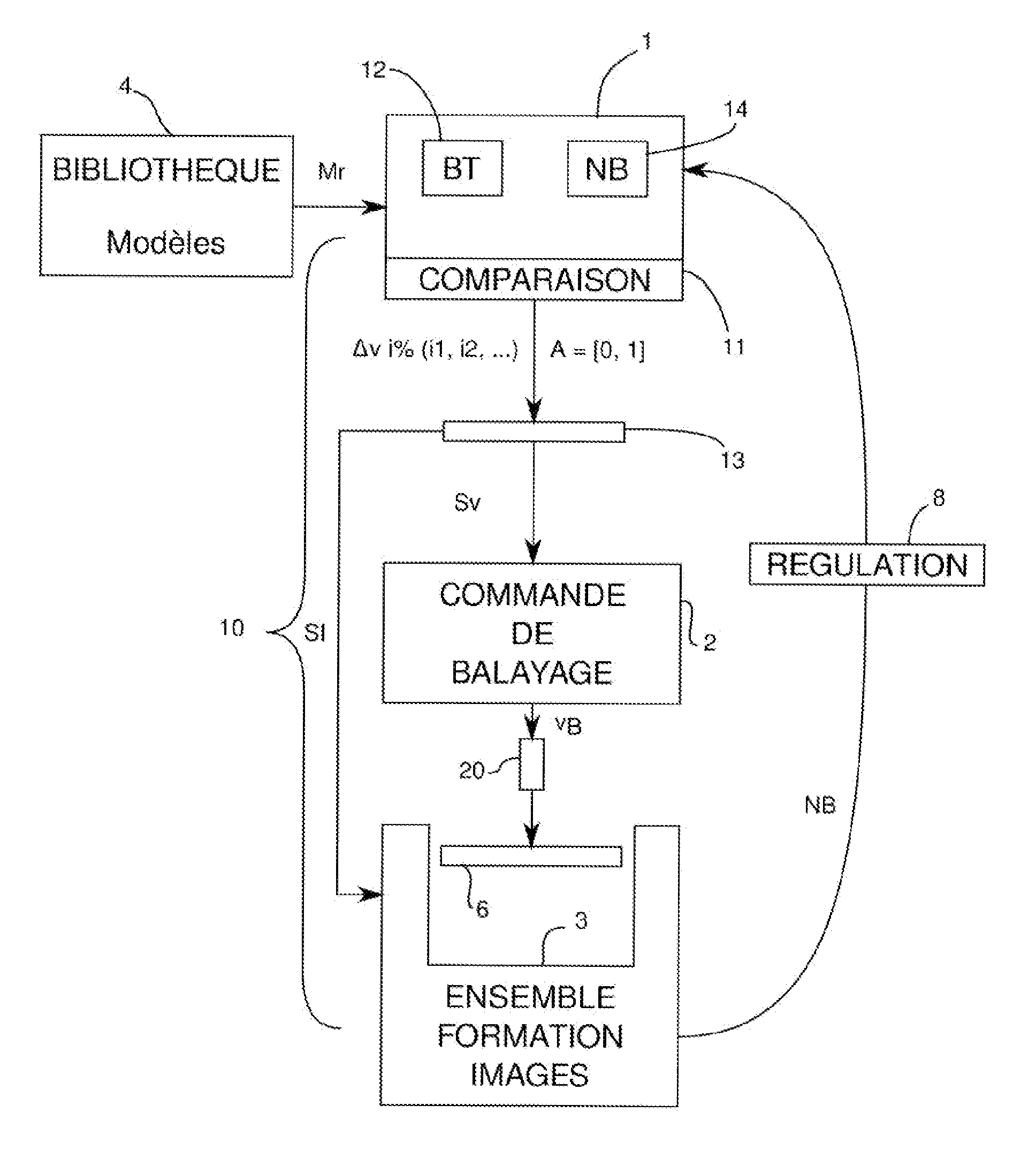
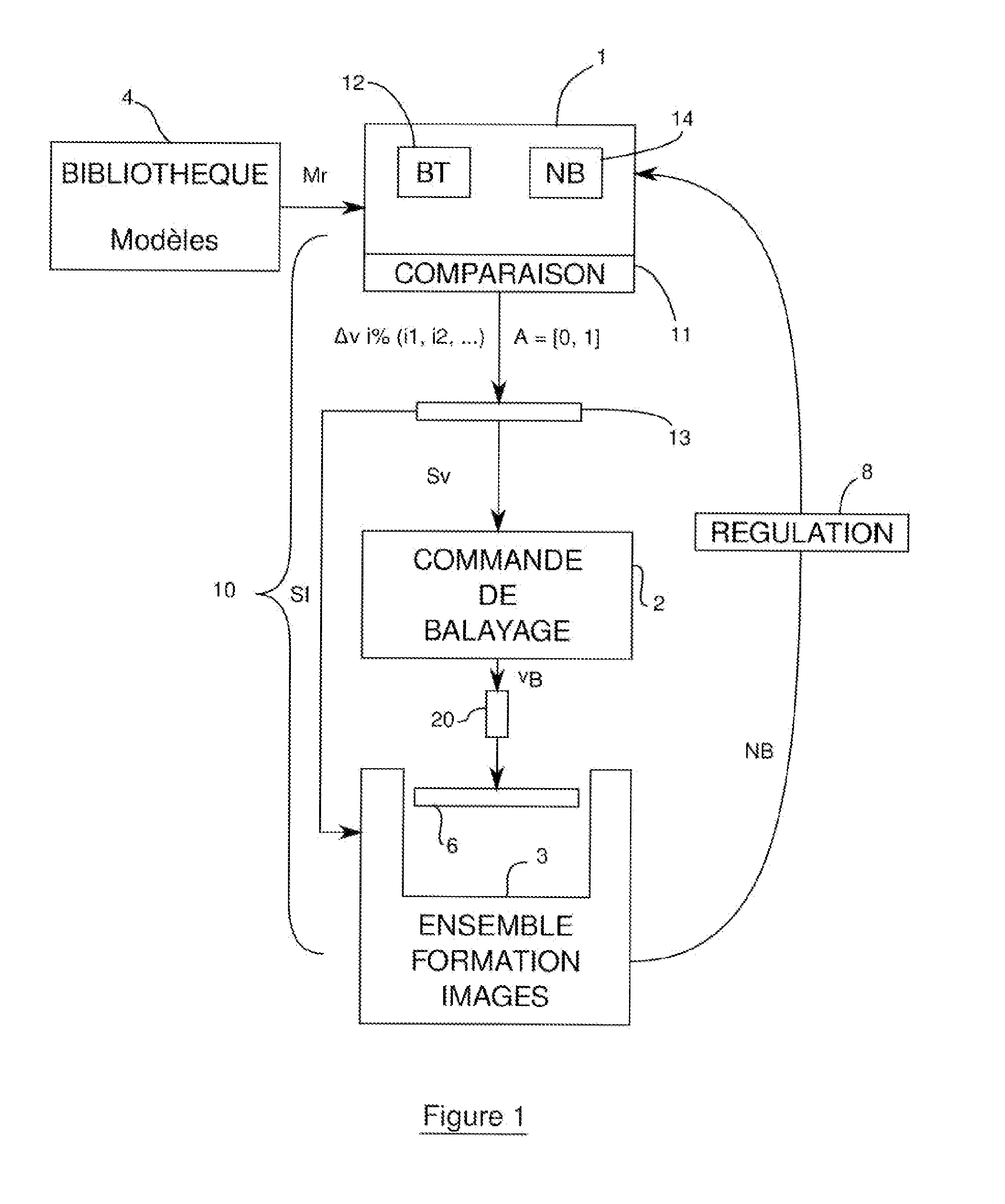
[0036]With reference to the diagram of FIG. 1, a system 10 according to the invention includes a digital data processing unit 1 having a processor and memories. This unit provides a sweep speed signal Sv to a sweep controller 2 of a high-pressure abrasive water jet machine 20. In this non-limiting example, the sweep speed is the parameter used to vary the machining depth. An assembly 3 for forming digital images of a surface of a panel 6 of composite material to be machined is also controlled by means of orientation and light emission signals SI by the digital processing unit 1. This digital image forming assembly 3 supplies brightness levels NB of the illuminated panel surface to the data processing unit 1.

[0037]This processing unit 1 delivers indexings with increments of i % for the calculation of the speed signal Sv by adjustment of potentiometers 13. The controller 2 receives the signal Sv and supplies local sweep speed signals vB to the machine 20. The increments i % (i1, i2, ....


PUM

PropertyMeasurementUnit
Angleaaaaaaaaaa
Angleaaaaaaaaaa
Angleaaaaaaaaaa

Abstract

The invention relates to machine a component made of composite material in order to eliminate singularities, defects or damage to the component using a method that is repeatable and adaptable. To do this, it is proposed that the defects and their type be identified by image processing of the surface of the component and that the local machining rates at which the plies are machined be regulated at the function of this identification. According to one embodiment, a system (10) for the ply-by-ply machining of defects of a component made of composite material includes a numerical data processing unit (1) combined with a sweep control (2) that commands the sweep of a high-pressure water jet machine (20), and an image formation assembly (3) including an image capturing device (30, 31) connected with the numerical processing unit (1). The processing unit (1) includes regulating devices (11, 13) indexing local sweep rates, by convergence of brightness levels (NB) from the successive sweeps, these being formed by the image capturing assembly (3) toward making the brightness uniform according to a model (Mr) correlating brightness to ply state typology identification (BT) that can be supplied by a library (4). The correlation data (BT) and brightness levels (NB) are stored in memory modules (12, 14) of the processing unit (1).

Description

CROSS REFERENCE TO RELATED APPLICATION[0001]This application is a national stage entry of PCT / EP2013 / 001066 filed Apr. 12, 2013, under the International Convention, claiming priority over FR 1253665 filed Apr. 20, 2012.TECHNICAL FIELD[0002]The invention relates to a method for the ply-by-ply machining of components made of composite material, in the context of use in any machining process in which the appropriate amount of energy is applied to remove a given volume of material, particularly by means of a high-pressure water jet. The invention also relates to an optimization system adapted to use this method.[0003]The invention is applicable to panels of storage holds, frames or walls, intended particularly, but not exclusively, for the aeronautics industry. The invention relates particularly, but not exclusively, to the repair of these panels. It is also applicable to the shape machining of these panels with constant plies.[0004]The composite material is generally composed of a stac...

Claims


Application Information

Patent Timeline
IPC IPC(8): B24C1/04
CPCB24C1/04B29C73/10B29C73/26B29C2073/264G01N21/8806G01N2021/8438G01N2021/8472
Inventor DELERIS, MICHELCENAC, FRANCOIS
Owner JEDO TECH
Learn More