
Process and apparatus for making tufted article

a technology of injection molding machine and tufted article, which is applied in the direction of manufacturing tools, food shaping, drawing profiling tools, etc., can solve the problems of increasing pressure, reducing the effective cooling of the material by the mold cavity walls, and increasing the cost of equipment, so as to achieve the effect of increasing the cost and performance of equipmen

Inactive Publication Date: 2015-04-09
THE PROCTER & GAMBLE COMPANY
View PDF10 Cites 20 Cited by
  • Summary
  • Abstract
  • Description
  • Claims
  • Application Information

AI Technical Summary

Benefits of technology

The disclosed process and apparatus for low-constant-pressure injection-molding use a pressure-dominated algorithm to control melt pressure, which offers advantages over conventional high-variable-pressure injection-molding processes. It is more cost-effective and efficient, allowing manufacturers to use simpler mold structures and more cost-effective materials, as well as a more robust processing method that is less sensitive to variations in material properties. This allows for the production of quality injection-molded products at constant low pressures without premature hardening of the thermoplastic material and without the need to heat or maintain constant temperatures in the mold cavity.

Problems solved by technology

As material freezes, it also shrinks, pulling away from the mold cavity walls, which reduces effective cooling of the material by the mold cavity walls.
Increasing the pressure, however, has both cost and performance downsides.
As the pressure required to mold the component increases, the molding equipment must be strong enough to withstand the additional pressure, which generally causes the equipment to be more expensive.
A manufacturer may have to purchase new equipment to accommodate these increased pressures, which naturally results in significant capital expenses.
These machines have multi-cavity molds and complex cooling systems to increase production rates.
But high-hardness materials, such as most tool steels, have relatively low thermal conductivities, generally less than 20 BTU / HR FT ° F., which leads to long cooling times as heat is transferred from the molten plastic material through the high hardness material.

Method used


Image

  • Process and apparatus for making tufted article
  • Process and apparatus for making tufted article
  • Process and apparatus for making tufted article

Examples


Embodiment Construction

[0018]As used herein, the following terms have the following meanings.

[0019]The term “low pressure” of a thermoplastic material means melt pressures of 6000 psi and lower, as measured at an injection nozzle of an injection-molding apparatus. A reference to pressure “measured at a nozzle” (and the like) refer to measurements of the molten material's pressure taken upstream the exit orifice of the injection nozzle, either inside the injection nozzle or in an area immediately upstream the injection nozzle.

[0020]The term “gate size” generally refers to the cross-sectional area of a gate, which is formed by the intersection of the runner and the mold cavity. For hot-runner systems, the gate can be of an open design, where there is no positive shut off of the flow of material at the gate—or a closed design, where a valve pin is used to mechanically shut off the flow of material through the gate in to the mold cavity. (The latter type of gate is also conventionally known as a “valve gate.”...


PUM

PropertyMeasurementUnit
Fractionaaaaaaaaaa
Fractionaaaaaaaaaa
Fractionaaaaaaaaaa

Abstract

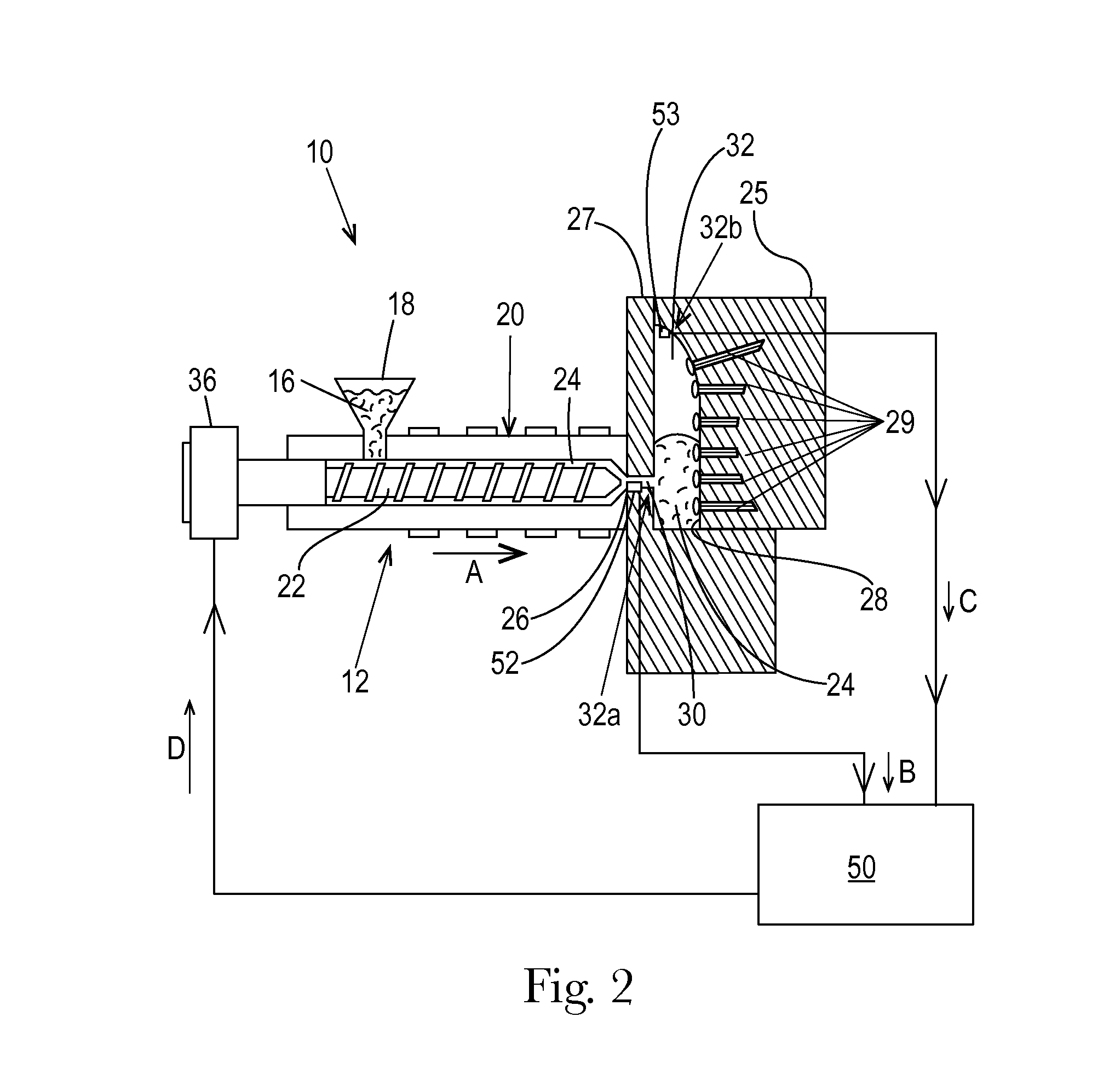
A process for making a tufted article from a thermoplastic material comprises controlling injection pressure according to a pressure-dominated algorithm including detecting at least 100 melt-pressure measurements per second upstream a front end of a mold cavity. An apparatus comprises a pressure-control mechanism for monitoring and adjusting an injection pressure according to the pressure-dominated algorithm, wherein the pressure-control mechanism comprises at least one high-frequency pressure sensor located upstream the mold cavity's front end.

Description

TECHNICAL FIELD[0001]The present invention relates to injection-molding machines and methods for producing tufted articles by injection molding, and more particularly to injection-molding processes and apparatuses wherein low-pressure injection molding is controlled by a pressure-dominated algorithm.BACKGROUND[0002]Injection molding is a technology commonly used for high-volume manufacturing of parts made of meltable material, most commonly of parts made of thermoplastic polymers. A typical injection-molding procedure comprises basic operations of heating a plastic material in an injection-molding machine to allow the plastic to flow under pressure, injecting the melted plastic into a mold cavity or cavities defined between two mold parts that have been closed, allowing the plastic under pressure to cool and harden in the cavity or cavities, opening the mold cavity or cavities, and ejecting the molded article from the mold. Each mold cavity may be connected to a flow channel by a ga...

Claims


Application Information

Patent Timeline
IPC IPC(8): B29C45/14
CPCB29C45/14B29L2031/42B29C45/77B29C2945/76006B29C2945/76287B29C2945/76381B29C2945/76384A46B3/06A46D3/005
Inventor NEWMAN, MATTHEW LLOYDALTONEN, GENE MICHAELGUSTAFSON, CASEY JOSEPH
Owner THE PROCTER & GAMBLE COMPANY
Learn More