
Heat pump system for vehicle

Inactive Publication Date: 2015-04-02
HYUNDAI MOTOR CO LTD
View PDF4 Cites 18 Cited by
  • Summary
  • Abstract
  • Description
  • Claims
  • Application Information

AI Technical Summary

Benefits of technology

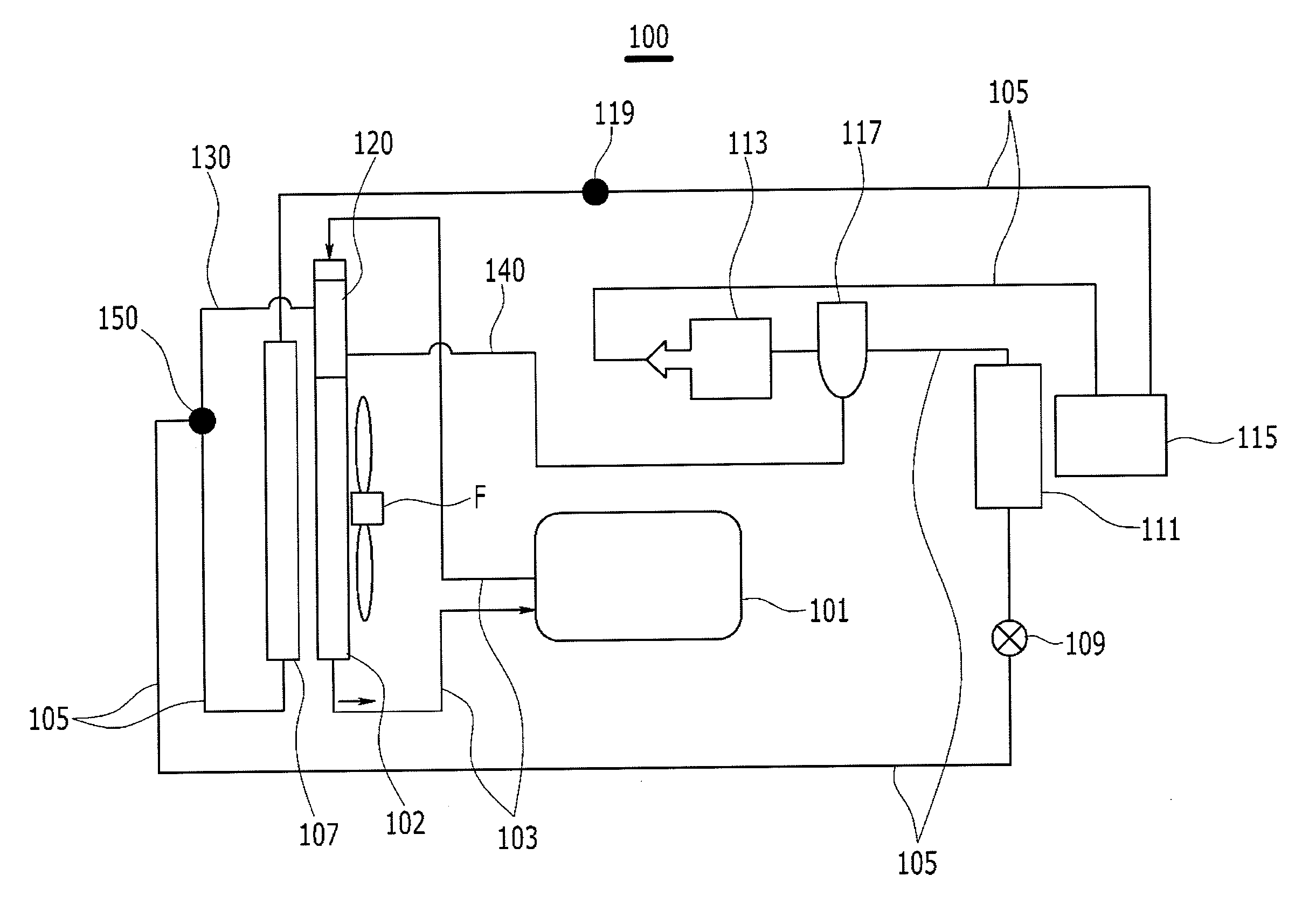
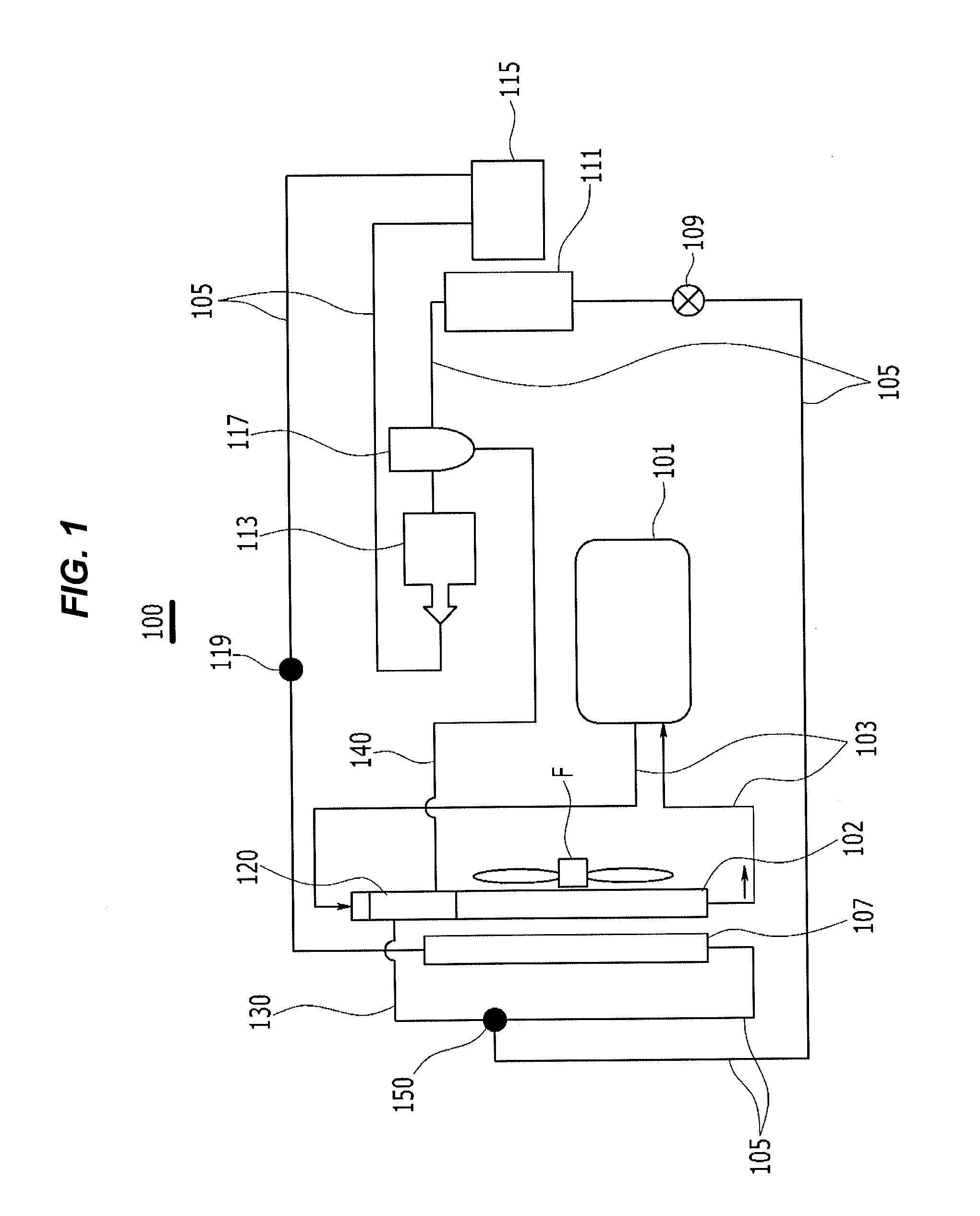
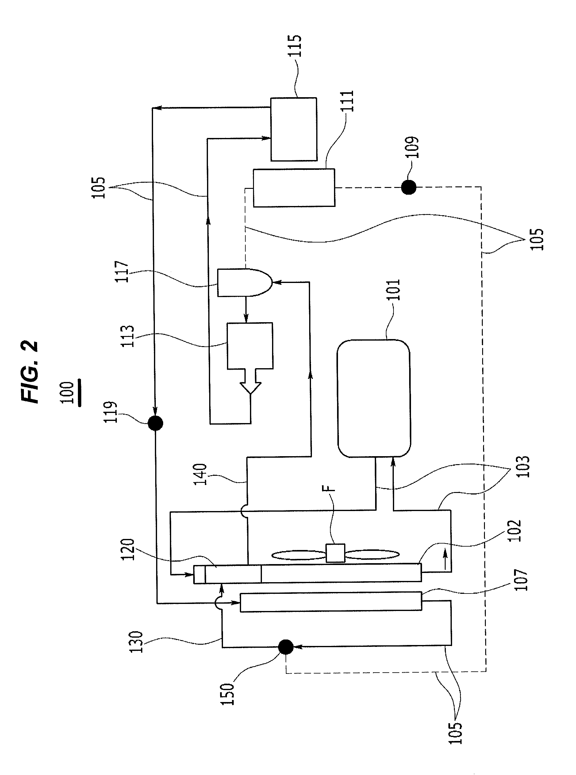
The present invention provides a heat pump system for a vehicle that integrates a water cooling type chiller with a radiator in which a coolant circulates. This simplifies the system by eliminating the need for additional piping and valves, reducing costs, improving performance, and increasing efficiency. By using the waste heat source, noise is reduced, heating performance is improved, and overall efficiency of the system is increased, resulting in a longer travel distance for the vehicle. The radiator and chiller are integrally configured, improving space utilization and decreasing electricity consumption.

Problems solved by technology

However, since the aforementioned heat pump system of the related art adopts an air cooling type in which outside air is used as a heat exchange medium for exchanging heat with a refrigerant, structures of heat exchangers including the compressor and structures of respective constituent elements are complicated, lengths of piping that connects the respective constituent elements are increased, and thereby, there is a problem in that an overall system package is complicated.
Because a heat source is not sufficient to convert the liquid refrigerant into the gaseous refrigerant when the liquid refrigerant is sucked into the compressor from the outdoor condenser, there are problems in that compression efficiency deteriorates, heating performance is significantly degraded when an outside air temperature is low, a system is unstable, and durability of the compressor deteriorates when the liquid refrigerant flows into the compressor.
In addition, since a heating operation needs to be performed with only the PTC heater, there are also problems in that heating performance greatly deteriorates, a travel distance is shortened by an increase in heating load due to an increase in amount of power consumption, and travel performance deteriorates because of a malfunction of the entire system when the heat exchanger or the valve is damaged.

Method used


Image

  • Heat pump system for vehicle
  • Heat pump system for vehicle
  • Heat pump system for vehicle

Examples


Embodiment Construction

[0032]Reference will now be made in detail to various embodiments of the present invention(s), examples of which are illustrated in the accompanying drawings and described below. While the invention(s) will be described in conjunction with exemplary embodiments, it will be understood that present description is not intended to limit the invention(s) to those exemplary embodiments. On the contrary, the invention(s) is / are intended to cover not only the exemplary embodiments, but also various alternatives, modifications, equivalents and other embodiments, which may be included within the spirit and scope of the invention as defined by the appended claims.

[0033]Throughout the specification and the claims, unless explicitly described to the contrary, the word “comprise” and variations such as “comprises” or “comprising” will be understood to imply the inclusion of stated elements but not the exclusion of any other elements.

[0034]In addition, “unit”, “means”, “part”, “member”, or the lik...


PUM


Abstract

A heat pump system includes air conditioning devices to adjust operations of cooling and heating a vehicle interior by circulating a refrigerant in accordance with a heating mode and a cooling mode of an electric vehicle, includes an outdoor condenser configured to condense the refrigerant, an expansion valve configured to expand the refrigerant condensed by the outdoor condenser, an evaporator configured to evaporate the refrigerant expanded by the expansion valve, a compressor configured to compress the refrigerant evaporated by the evaporator, and an indoor condenser configured to primarily condense the refrigerant compressed by the compressor and connected to the outdoor condenser. The heat pump system may further include: a radiator connected to electronic equipment; a chiller configured integrally with the radiator; first connecting piping connecting the refrigerant piping and the chiller; and second connecting piping connecting the refrigerant from the chiller to the refrigerant piping.

Description

CROSS-REFERENCE TO RELATED APPLICATION[0001]The present application claims priority of Korean Patent Application Number 10-2013-0115597 filed Sep. 27, 2013, the entire contents of which application is incorporated herein for all purposes by this reference.BACKGROUND OF INVENTION[0002]1. Field of Invention[0003]The present invention relates to a heat pump system for a vehicle, and more particularly, to a heat pump system for a vehicle in which a water cooling type chiller is integrally configured with a radiator, and a refrigerant selectively passes through the chiller in accordance with a heating mode or a cooling mode of a vehicle, thereby improving overall efficiency of a system, shortening a piping length, and simplifying constituent elements.[0004]2. Description of Related Art[0005]In general, an air conditioner for a vehicle includes an air conditioning module for cooling and heating an interior of the vehicle.[0006]In a process in which a heat exchange medium discharged by an ...

Claims


Application Information

Patent Timeline
IPC IPC(8): B60H1/00F25B41/42
CPCB60H1/00007B60H1/00021B60H2001/00107B60H1/00385B60H1/00921B60H2001/00949F25B6/04F25B2339/047B60H1/00392B60H1/323F01P3/18
Inventor KIM, YOUNG JUNLEE, KILWOO
Owner HYUNDAI MOTOR CO LTD
Learn More