Methods and structures for reducing carbon oxides with non ferrous catalysts
a carbon dioxide and catalyst technology, applied in the direction of metal/metal-oxide/metal-hydroxide catalysts, fullerenes, natural mineral layered products, etc., can solve the problems of significant cost of carbon dioxide capture and sequestration, and the cost of manufacture of cnts, so as to simplify the setup of the reactor and reduce costs.
- Summary
- Abstract
- Description
- Claims
- Application Information
AI Technical Summary
Benefits of technology
Problems solved by technology
Method used
Image
Examples
example 1
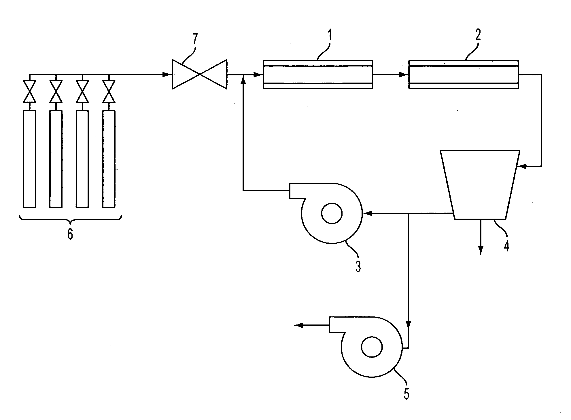
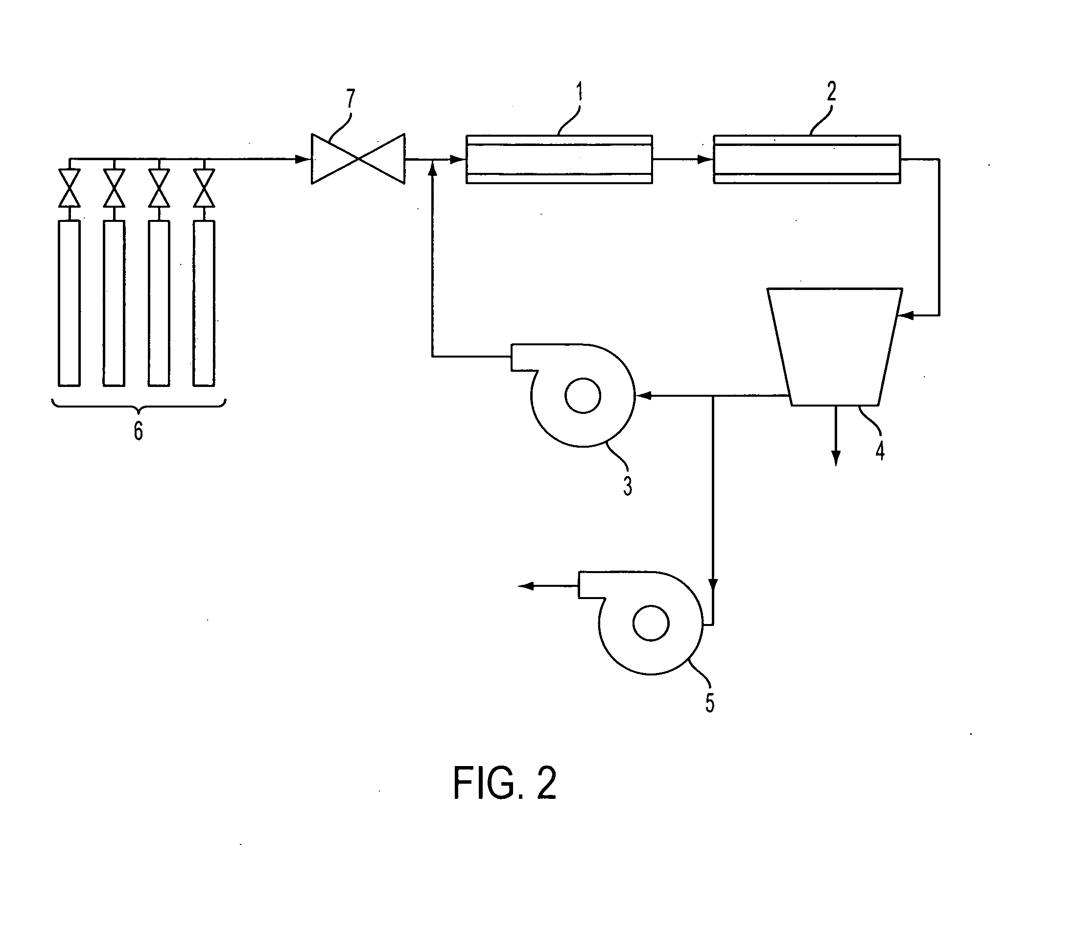
[0136]A sample of mild steel wafer with extensive red rust spots was used as the catalyst. The mild steel wafer was placed in the tube furnace 1 at approximately the centerline. The vacuum pump 5 was started, and helium was used to purge the experimental apparatus for five minutes. After five minutes, the vacuum pump 5 was turned off, the compressor 3 was turned on, the refrigerated condenser 4 was turned on, and the helium gas continued to flow until the pressure reached 90.6 kPa (680 Torr), at which point the gas flow was shut off. The heating element of the tube furnace 1 was then turned on.
[0137]When the furnace 1 temperature reached a temperature of 680° C., the vacuum pump 5 was turned on, and reaction gases in a stoichiometric mixture of carbon dioxide and hydrogen (delivered from the gas supply 6 by the mixing valve 7) were used to purge the experimental apparatus for five minutes. After five minutes, the vacuum pump 5 was turned off. When the experimental apparatus reached ...
example 2
[0139]A quartz disk was placed lying flat on a wafer of 304 stainless steel, which was used as the catalyst. The wafer was placed in furnace 1 at approximately the centerline. The experimental apparatus was helium-purged and heated as in Example 1. Reaction gases were added and recirculated for one hour at a temperature of 680° C. and a pressure between 85.3 kPa (640 Torr) and 101.3 kPa (760 Torr), as in Example 1.
[0140]The stainless steel sample was removed from the furnace 1 after the furnace 1 had cooled. A mat of CNTs had grown between the quartz and the stainless steel wafer. Portions of the CNT mat adhered to both the quartz and the stainless steel surfaces. FIG. 7 shows the sample under 10,000× magnification, and FIG. 8 shows the sample under 100,000× magnification. The size of the CNTs (tens to hundreds of nanometers in diameter) indicates that they are probably multi-wall CNTs.
example 3
[0141]A wafer of 316L stainless steel was used as the catalyst. The 316L stainless steel wafer was placed in furnace 1 at approximately the centerline. The experimental apparatus was helium-purged and heated as in Example 1. Reaction gases were added and recirculated for one hour as in Example 1, but at a temperature of 700° C. and a pressure between 93.3 kPa (700 Torr) and 97.3 kPa (730 Torr).
[0142]The stainless steel wafer was removed from the furnace 1 after the furnace 1 had cooled. FIG. 9 is a photograph of the stainless steel wafer. The carbon nanotubes grew on only a portion of the wafer. The reasons for this are unclear. FIG. 10 shows an image of a region of the CNT forest on the wafer at 2,500× magnification, and FIG. 11 shows an image of the same region of the CNT forest at 10,000× magnification. The diameter of the tubes indicates that they are likely multi-wall CNTs.
PUM
| Property | Measurement | Unit |
|---|---|---|
| temperature | aaaaa | aaaaa |
| temperature | aaaaa | aaaaa |
| mean particle size | aaaaa | aaaaa |
Abstract
Description
Claims
Application Information
 - R&D
- Intellectual Property
- Life Sciences
- Materials
- Tech Scout
- Unparalleled Data Quality
- Higher Quality Content
- 60% Fewer Hallucinations
Browse by: Latest US Patents, China's latest patents, Technical Efficacy Thesaurus, Application Domain, Technology Topic, Popular Technical Reports.
© 2025 PatSnap. All rights reserved.Legal|Privacy policy|Modern Slavery Act Transparency Statement|Sitemap|About US| Contact US: help@patsnap.com


