
Acoustic transducer and microphone

Active Publication Date: 2015-03-19
MMI SEMICON CO LTD
View PDF10 Cites 29 Cited by
  • Summary
  • Abstract
  • Description
  • Claims
  • Application Information

AI Technical Summary

Benefits of technology

The present invention provides an acoustic transducer that can maintain its frequency response and detect acoustic vibration without succumbing to damage caused by high air pressure. One feature of the invention is the use of a fixed electrode plate that is divided into multiple regions and a barrier electrode to prevent electrical signal leakage between these regions. This results in a more reliable and accurate detection of acoustic vibration.

Problems solved by technology

In general, the maximum input sound pressure of a microphone is limited by the harmonic distortion rate (total harmonic distortion).
This is because when a microphone attempts to detect a sound having a high sound pressure, harmonic distortion occurs in the output signal, and the sound quality and precision become impaired.
However, in general microphones, there is a trade-off relationship between an improvement in the acoustic vibration detection sensitivity and a reduction in the harmonic distortion rate, and it has been difficult to provide a microphone with a wide dynamic range from low-volume (low sound pressure) sounds to high-volume (high sound pressure) sounds.
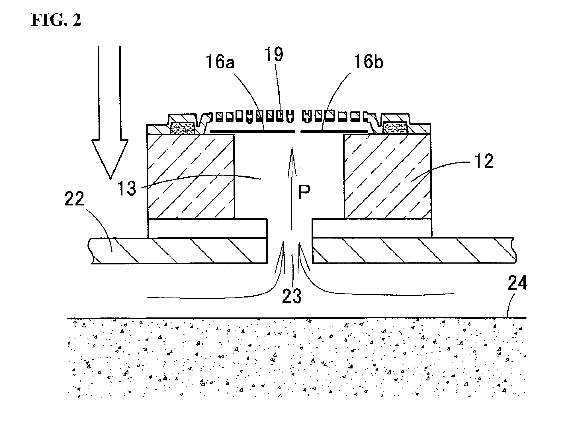
In particular, as shown in FIG. 3C, the second diaphragm 16b for high-volume sounds has increased rigidity and a reduced area in order to operate optimally in the case of high sound pressure, and therefore is likely to become damaged due to undergoing steep deformation and the occurrence of large distortion.

Method used


Image

  • Acoustic transducer and microphone
  • Acoustic transducer and microphone
  • Acoustic transducer and microphone

Examples


embodiment 1

Variations of Embodiment 1

[0107]A variation of Embodiment 1 of the present invention will be described below with reference to FIGS. 15 to 18. FIG. 15A is a plan view showing an acoustic sensor according to a variation of Embodiment 1 of the present invention, in a state in which the back plate has been removed. In this variation, a circular opening 33c is provided in the substantially central portion of the first diaphragm 33a. When the first diaphragm 33a is not undergoing deformation, the circular regulation portion 37 provided on the lower end of the support portion 48 extending downward from the back plate 38 is located inside the opening 33c and blocks the opening 33c. Note that a slit-shaped opening 56 is for separating the first diaphragm 33a and the second diaphragm 33b, and extends parallel to the short side direction of the diaphragm 33.

[0108]In the variation shown in FIG. 15A, the first diaphragm 33a and the second diaphragm 33b undergo large deformation when high-load p...

embodiment 2

[0115]FIG. 19A is a plan view showing an acoustic sensor 61 according to Embodiment 2 of the present invention, in a state in which a back plate 38 has been removed. FIG. 19B is a schematic cross-sectional diagram showing a state in which high-load pressure P has been applied to the acoustic sensor 61. In the acoustic sensor 61 of Embodiment 2, recessions 62 that are recessed toward the interior of the diaphragm 33 in the shape of a notch (void portions for allowing pressure to escape) are formed in the sides (outer peripheral portions) of the diaphragm 33 as shown in FIG. 19A. Specifically, the recessions 62 are provided in regions between adjacent leg pieces 46 on the sides of the first diaphragm 33a that are not adjacent to the second diaphragm 33b. Alternatively, the recessions 62 may be provided on the long side of the second diaphragm 33b that is not adjacent to the first diaphragm 33a, or the recessions 62 may be provided on the sides of both the first diaphragm 33a and the s...

embodiment 3

[0118]FIG. 20A is a schematic cross-sectional diagram of an acoustic sensor 71 according to Embodiment 3 of the present invention. FIG. 20B is a plan view of the acoustic sensor 71 in a state in which the back plate 38 has been removed. In the acoustic sensor 71 of Embodiment 3, a barrier electrode 72 is provided in a region of the lower surface of the back plate 38 that opposes the regulation portion 37. The barrier electrode 72 is formed by a conductive polysilicon thin film, and is created using the same material and the same process as the first fixed electrode plate 39a and the second fixed electrode plate 39b in the manufacturing process for the acoustic sensor 71. The barrier electrode 72 extends along the boundary between the first diaphragm 33a and the second diaphragm 33b, that is to say substantially from end to end along the length direction of the regulation portion 37. Note that the barrier electrode 72 may be grounded, or may be kept at a certain potential.

[0119]If th...


PUM


Abstract

An acoustic transducer has a substrate having a cavity, a vibrating electrode plate disposed above the substrate and having a void portion that allows pressure to escape, a fixed electrode plate disposed above the substrate opposite the vibrating electrode plate, a plurality of sensing portions configured by the vibrating electrode plate and the fixed electrode plate, at least one of the vibrating electrode plate and the fixed electrode plate being divided into a plurality of regions, and a sensing portion being configured by the vibrating electrode plate and the fixed electrode plate in each of the divided regions, and a leak pressure regulation portion that hinders leakage of air pressure passing through the void portion when the vibrating electrode plate is not undergoing deformation.

Description

BACKGROUND[0001]1. Field[0002]The present invention relates to an acoustic transducer and a microphone. Specifically, the present invention relates to a capacitance type of acoustic transducer configured by a capacitor structure made up of a vibrating electrode plate (diaphragm) and a fixed electrode plate. The present invention also relates to a microphone that employs this acoustic transducer. In particular, the present invention relates to a very small-sized acoustic transducer created using MEMS (Micro Electro Mechanical System) technology.[0003]2. Related Art[0004]In recent years, there has been demand for microphones to detect sounds with high sensitivity in a range from low sound pressure to high sound pressure. In general, the maximum input sound pressure of a microphone is limited by the harmonic distortion rate (total harmonic distortion). This is because when a microphone attempts to detect a sound having a high sound pressure, harmonic distortion occurs in the output sig...

Claims


Application Information

Patent Timeline
IPC IPC(8): H04R19/04
CPCH04R19/04H01L2224/48137H01L2924/15151H04R19/005
Inventor UCHIDA, YUKI
Owner MMI SEMICON CO LTD
Learn More