
System and Method for Powering Multiple Electronic Devices Operating Within an Immersion Cooling Vessel

Active Publication Date: 2015-03-12
DELL PROD LP
View PDF18 Cites 49 Cited by
  • Summary
  • Abstract
  • Description
  • Claims
  • Application Information

AI Technical Summary

Benefits of technology

This patent describes a system for cooling electronic components, such as servers, by using a volatile liquid. The system includes an immersion tank with a power distribution unit that provides power to the electronic components while preventing electrical arcing and other problems. The tank also has a condensation surface above the liquid level, which prevents condensation fluid from leaking into the tank and coming into contact with the power distribution unit. The system can be used in a two-phase heat transfer immersion cooling system for servers, with a power distribution system embedded in the server rack for hot plugging power. The system ensures that the electronic components are cooled efficiently without causing damage or malfunctions. Its technical effects include improved cooling efficiency, prevented electrical arcing, and reliable power distribution for servers and other electronic components.

Problems solved by technology

The condensation liquid is a lower density than the dielectric fluid, such that leakage of the condensation fluid into the tank volume results in the condensation fluid floating atop the dielectric liquid.

Method used


Image

  • System and Method for Powering Multiple Electronic Devices Operating Within an Immersion Cooling Vessel
  • System and Method for Powering Multiple Electronic Devices Operating Within an Immersion Cooling Vessel
  • System and Method for Powering Multiple Electronic Devices Operating Within an Immersion Cooling Vessel

Examples


Embodiment Construction

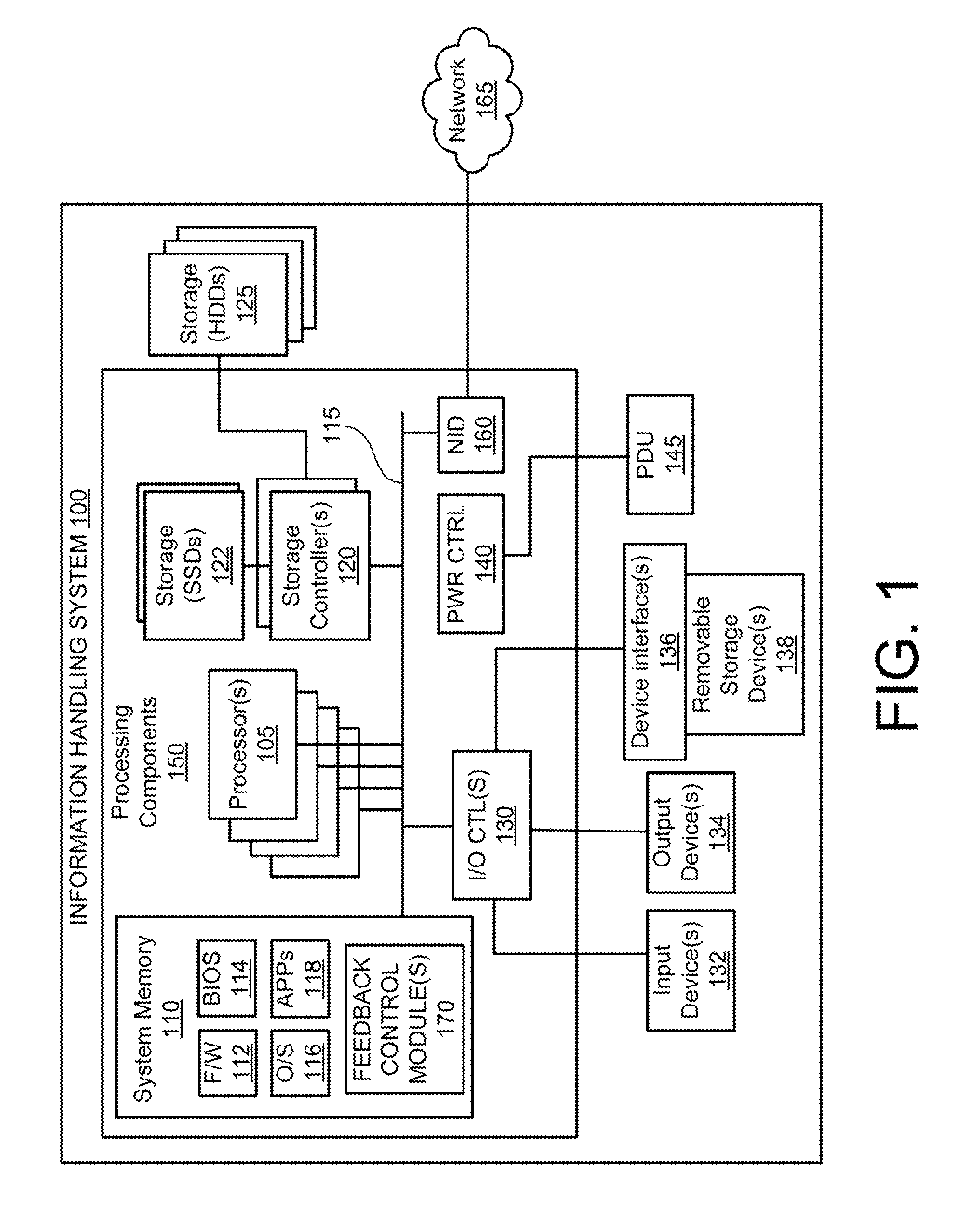
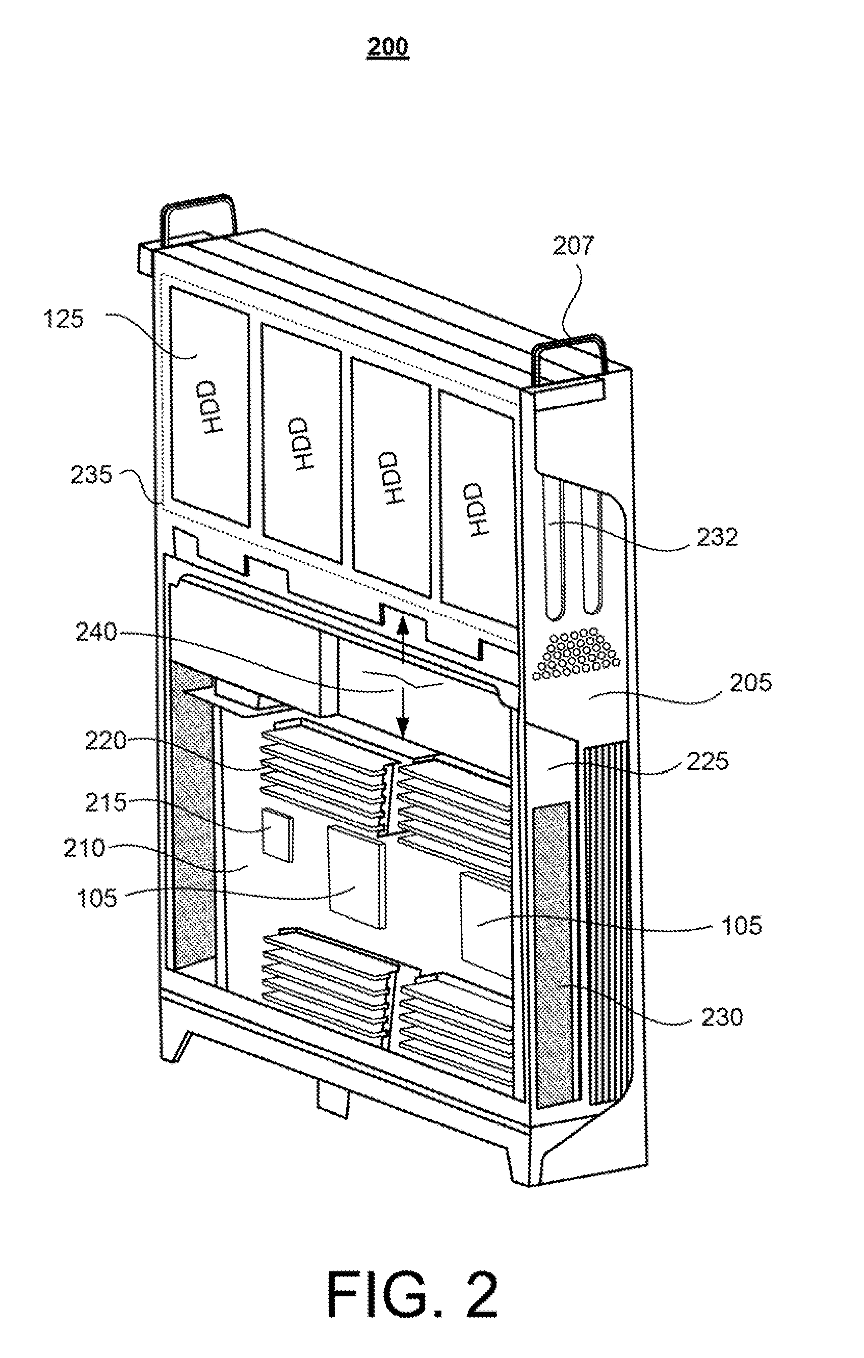
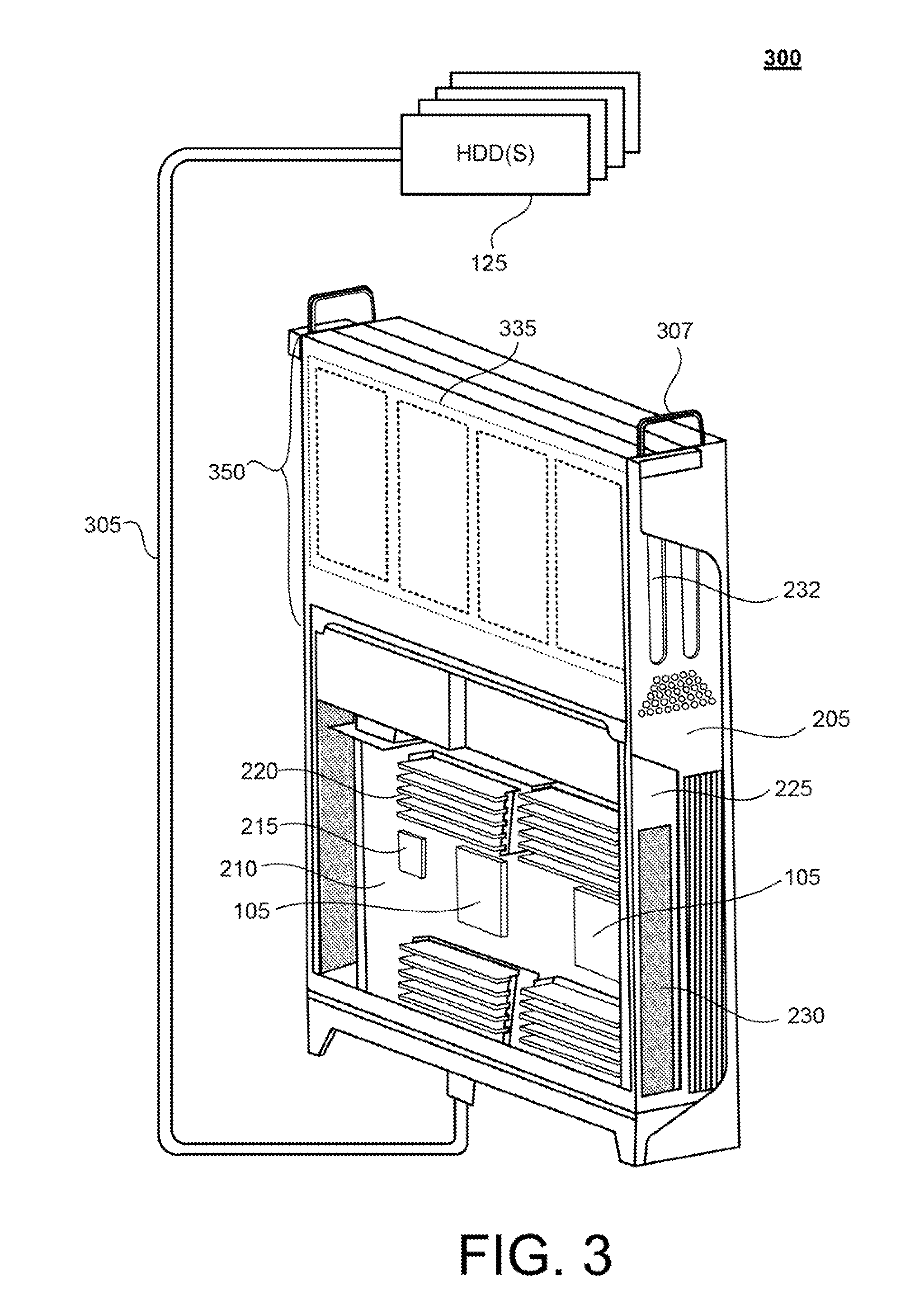
[0040]The present disclosure provides illustrative embodiments of various aspects of and / or different configurations and implementations of one or more systems, methods, and multi-phase heat transfer immersion cooling vessels that enable direct cooling of information handling systems, such as servers, by submerging at least a portion of the physical information handling systems in a dielectric liquid within a multi-phase heat transfer immersion cooling vessel.

[0041]The disclosure generally includes a plurality of different aspects and multiple different embodiments, and each aspect along with the associated embodiments are described in detail below within one of the titled Sections A-K. A first aspect of the general disclosure, presented in Section A, provides examples of an information handling system and of two different servers configured and / or oriented for use within a rack-based immersion cooling system. Section B, which describes the second aspect of the general disclosure, i...


PUM


Abstract

An immersion cooling tank comprises: a dielectric liquid disposed within a lower volume of the tank; at least one electronic equipment immersed within the dielectric liquid and which requires electrical power to operate; and at least one power distribution unit and / or a bus bar distribution system submerged beneath a surface of the dielectric liquid and providing electrical power to the at least one electronic equipment. The immersion cooling tank further includes a condenser located vertically above the dielectric fluid and the at least one electronic equipment, and through which is flowing a condensation fluid that has a lower density than the dielectric liquid. A leak of the condensation fluid into the tank volume results in the condensation fluid floating atop the dielectric liquid and prevents the condensation liquid from coming into contact with the power distribution unit. The bus bar distribution system enables blind mating of inserted electronic components.

Description

BACKGROUND[0001]1. Technical Field[0002]The present disclosure generally relates to information handling systems and in particular to a system and method for providing power to multiple information handling systems that are operated within an immersion cooling vessel. Still more particularly, aspects of the disclosure relate to a system and method for safely powering electronic devices within an immersion cooling vessel with localized non-dielectric condensation liquid flow.[0003]2. Description of the Related Art[0004]As the value and use of information continue to increase, individuals and businesses seek additional ways to process and store information. One option available to users is information handling systems. An information handling system generally processes, compiles, stores, and / or communicates information or data for business, personal, or other purposes thereby allowing users to take advantage of the value of the information. Because technology and information handling ...

Claims


Application Information

Patent Timeline
Patent Type & Authority Applications(United States)
IPC IPC(8): H05K7/20
CPCH05K7/203H05K7/20809H05K7/20818H05K7/20827
Inventor SHELNUTT, AUSTIN MICHAELCURLEE, JAMES D.BAILEY, EDMOND I.SEKEL, JOSEPH M.STUEWE, JOHN R.MILLS, RICHARD STEVEN
Owner DELL PROD LP
Learn More