
Wrap case for packaging

Inactive Publication Date: 2015-03-05
LEE TAE JUNG
View PDF34 Cites 3 Cited by
  • Summary
  • Abstract
  • Description
  • Claims
  • Application Information

AI Technical Summary

Benefits of technology

The present invention provides a wrap case for packaging paper pipes. The case has a shaft hole into which the paper pipe is inserted and fixed, eliminating the need for additional components to hold the pipe. The case is made from a recyclable material and does not require any harmful chemicals. The case is designed to prevent the paper pipe from moving inside and crushing during use. The case also includes a cutter to safely use the packaging. The technical effects of the invention are recycling ease, safety, and efficient use of packaging.

Problems solved by technology

When a user unwinds the wound wrap when in use, the wound roll moves inside of the case, so cutting the wrap properly becomes hard.
Since the related wrap case is made from paper, if the user holds the wrap tightly, the wrap case may be easily crushed, thus damaging the wrap accommodated inside of the wrap case.
When the user packs a predetermined container using a packaging wrap while holding the related wrap case with a hand, the metallic teeth of the wrap case may hurt the user's hand due to the user's carelessness.

Method used


Image

  • Wrap case for packaging
  • Wrap case for packaging
  • Wrap case for packaging

Examples


Embodiment Construction

[0019]The above-described purpose, features and advantages of the present invention will be apparent along with the following detailed descriptions. The exemplary embodiments of the present invention will be described with reference to the accompanying drawings.

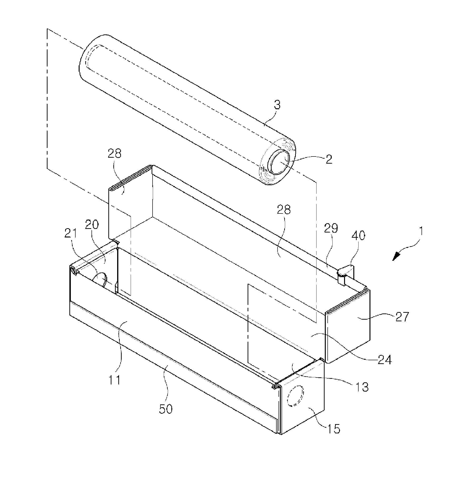
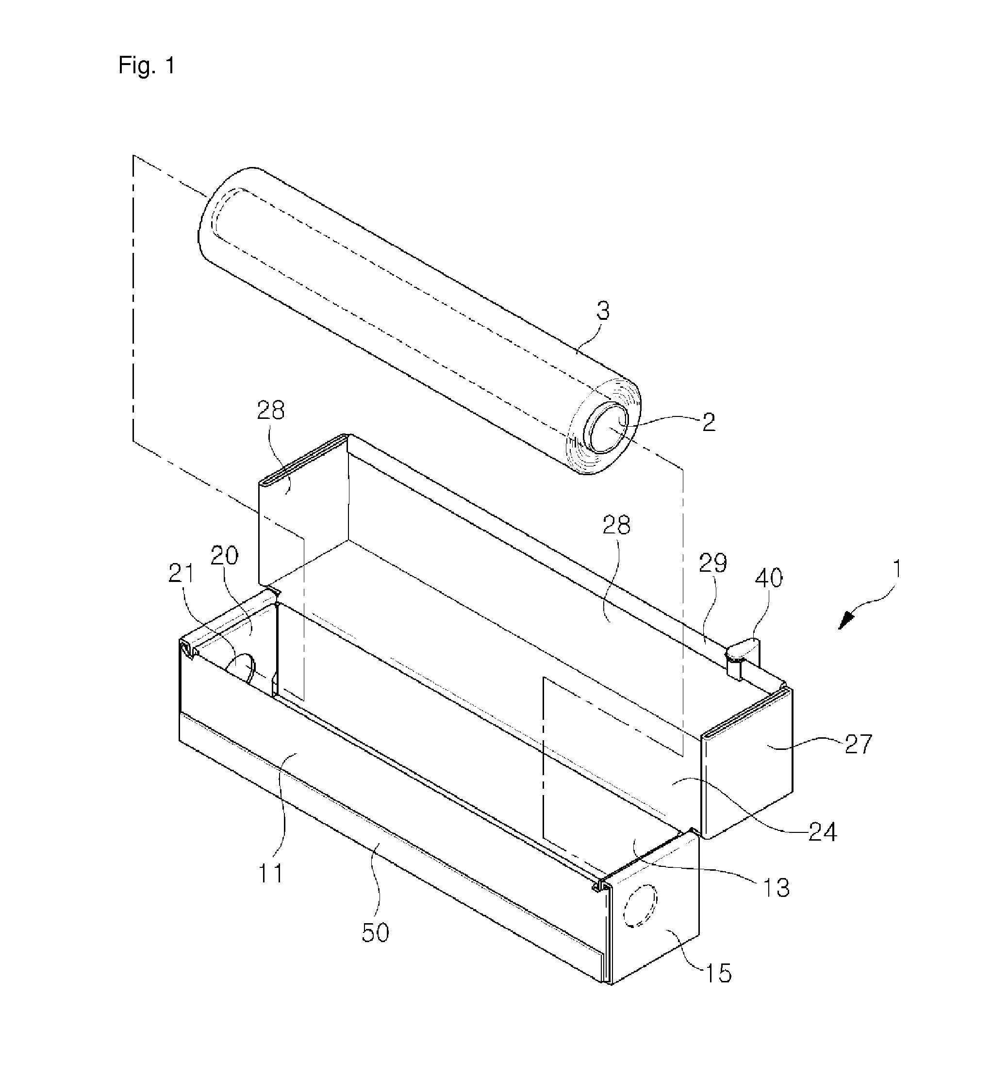
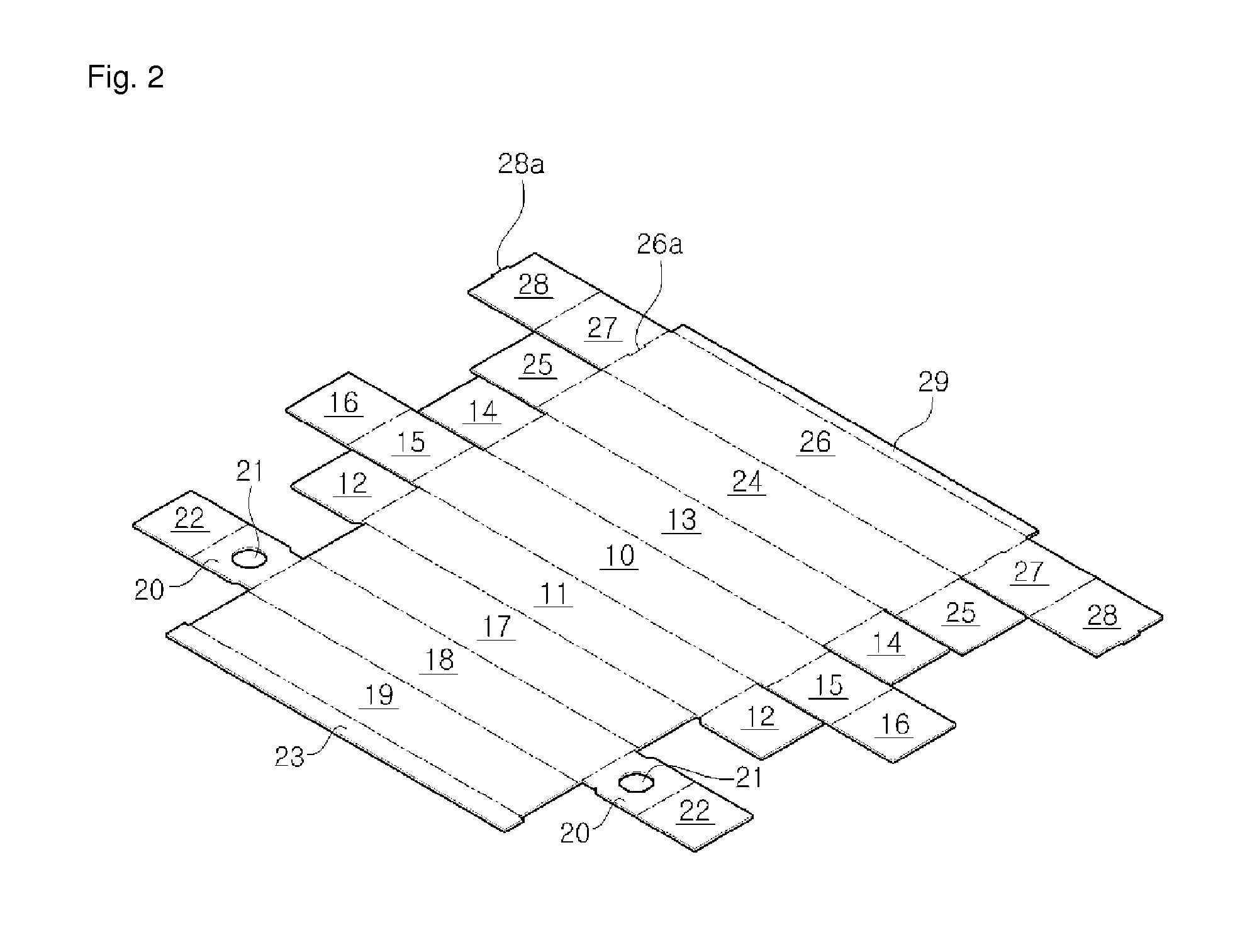
[0020]FIG. 1 is a perspective view illustrating a wrap case for packaging according to a first exemplary embodiment of the present invention. FIG. 2 is an exploded view according to a first exemplary embodiment of the present invention. FIG. 3 is a view illustrating a folded lateral cross section according to a first exemplary embodiment of the present invention. FIG. 4 is a lateral side view illustrating a state that a wrap is fixed according to a first exemplary embodiment of the present invention.

[0021]As illustrated therein, the wrap case 1 for packaging according to a first exemplary embodiment of the present invention is configured to accommodate a wrap 3 wound on a paper pipe 2. The wrap case 1 for packaging illustrate...


PUM


Abstract

The present invention relates to a wrap case (1) for packaging in which a wrap for packaging (3) wound around a branch pipe (2) is accommodated. The present invention comprises: a rectangular first bottom plate (10); a first front surface plate (11) and a first rear surface plate (13) which respectively extend from both long side portions of the first bottom plate (10); a first side surface plate (15) which extends from the short side portion of the first bottom plate (10); a first reinforcing plate (16) which extends from the outer side edge of the first side surface plate (15); connection plates (12 and 14) which extend from the short side portions of the first front surface plate (11) and the first rear surface plate (13); a second front surface plate (17) which extends from the long side portion of the first front surface plate (11) in such a manner as to overlap the first front surface plate (11); a second bottom plate (18) which extends from the long side portion of the second front surface plate (17) in such a manner as to overlap the first bottom plate (10); a second rear surface plate (19) which extends from the long side portion of the second bottom plate (18) in such a manner as to overlap the first rear surface plate (13); a second side surface plate (20) which extends from the short side portion of the second bottom plate (18) in such a manner as to overlap the first side surface plate (15); a second reinforcing plate (22) which extends from the outer side edge of the second side surface plate (20); an upper surface cover plate (24) which extends from the long side portion of the first rear surface plate (13); and a front surface cover plate (26) which extends from the long side portion of the upper surface cover plate (24). A shaft hole (21) is formed on the second side surface plate (20) or the second reinforcing plate (22) such that the end portion of the paper pipe (2) around which the wrap (3) is wound is inserted.

Description

TECHNICAL FIELD[0001]The present invention relates to a wrap case for packaging, and in particular to a wrap case for packaging, which is characterized in that a component for fixing a wrap is integrally provided, not separately, in order to fix the wrap, so the wrap is prevented from moving during the packaging of a predetermined thing, and a packaging work is easy, and the weight is light while effectively protecting the built-in wrap along with an easier recycling. Safety may be enhanced since metallic teeth are not used.BACKGROUND ART[0002]A predetermined container filled with food is generally sealed using a wrap in order to prevent the food from being oxidized as the food comes into direct contact with air. Such a wrap is a packaging material made from a synthetic resin in a form of film and is configured to maintain the freshness of food in such a way to seal the container containing a variety of foods.[0003]The related packaging wrap is wound on a cylindrical winding roll an...

Claims


Application Information

Patent Timeline
IPC IPC(8): B65D85/672
CPCB65D85/672B65D83/0882B65D5/5004B65H35/002B65H35/0086B65H2402/442B65H2402/443B65D25/52B65D83/08B65H35/04
Inventor LEE, TAE-JUNG
Owner LEE TAE JUNG
Learn More