Voltage regulating circuit and method thereof

a voltage regulation circuit and voltage regulation technology, applied in the direction of power conversion systems, electrically long antennas, antennas, etc., can solve the problems of amplitude fluctuation of output signals, and achieve the effect of reducing or eliminating the response time before a feedback loop entering a stable state, reducing the amplitude fluctuation, and reducing the curren

Inactive Publication Date: 2015-02-19
REALTEK SEMICON CORP
View PDF8 Cites 8 Cited by
  • Summary
  • Abstract
  • Description
  • Claims
  • Application Information

AI Technical Summary

Benefits of technology

The present invention is a voltage regulating circuit and method that uses a tank circuit to ensure a stable voltage during startup. Once the data signal output terminal enters a high impedance state, the tank circuit is disconnected from the output circuit and the fixed voltage of the tank circuit is locked at a level that provides a large current. When the data signal needs to be outputted, the tank circuit is connected to the output circuit, and the feedback loop is started. This results in a stable voltage that allows an output level to output a large current. This reduces or eliminates the response time before the feedback loop enters a stable state, which effectively reduces the amplitude fluctuation during the initial transmission stage of the data signal.

Problems solved by technology

However, a closed-loop bandwidth (CLBW) in the voltage regulator has a certain start time response, which results in an amplitude fluctuation of the output signal at an initial stage, for example, the amplitude is too small or too large.

Method used


Image

  • Voltage regulating circuit and method thereof
  • Voltage regulating circuit and method thereof
  • Voltage regulating circuit and method thereof

Examples


Embodiment Construction

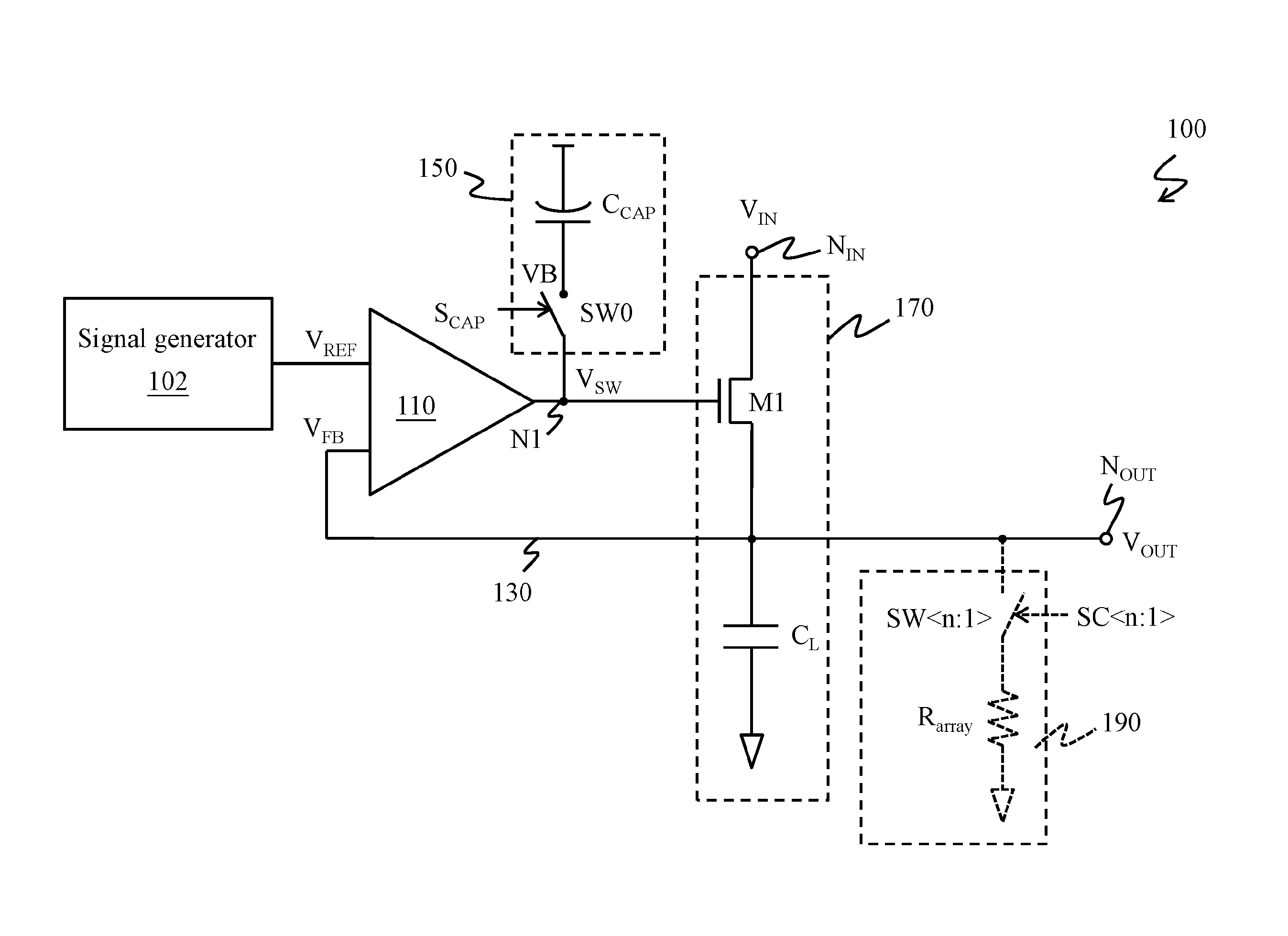
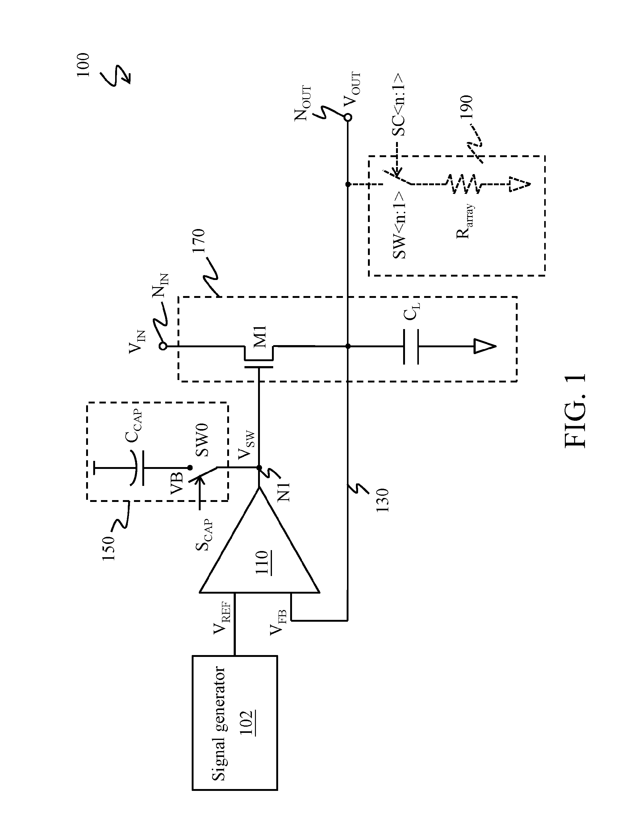
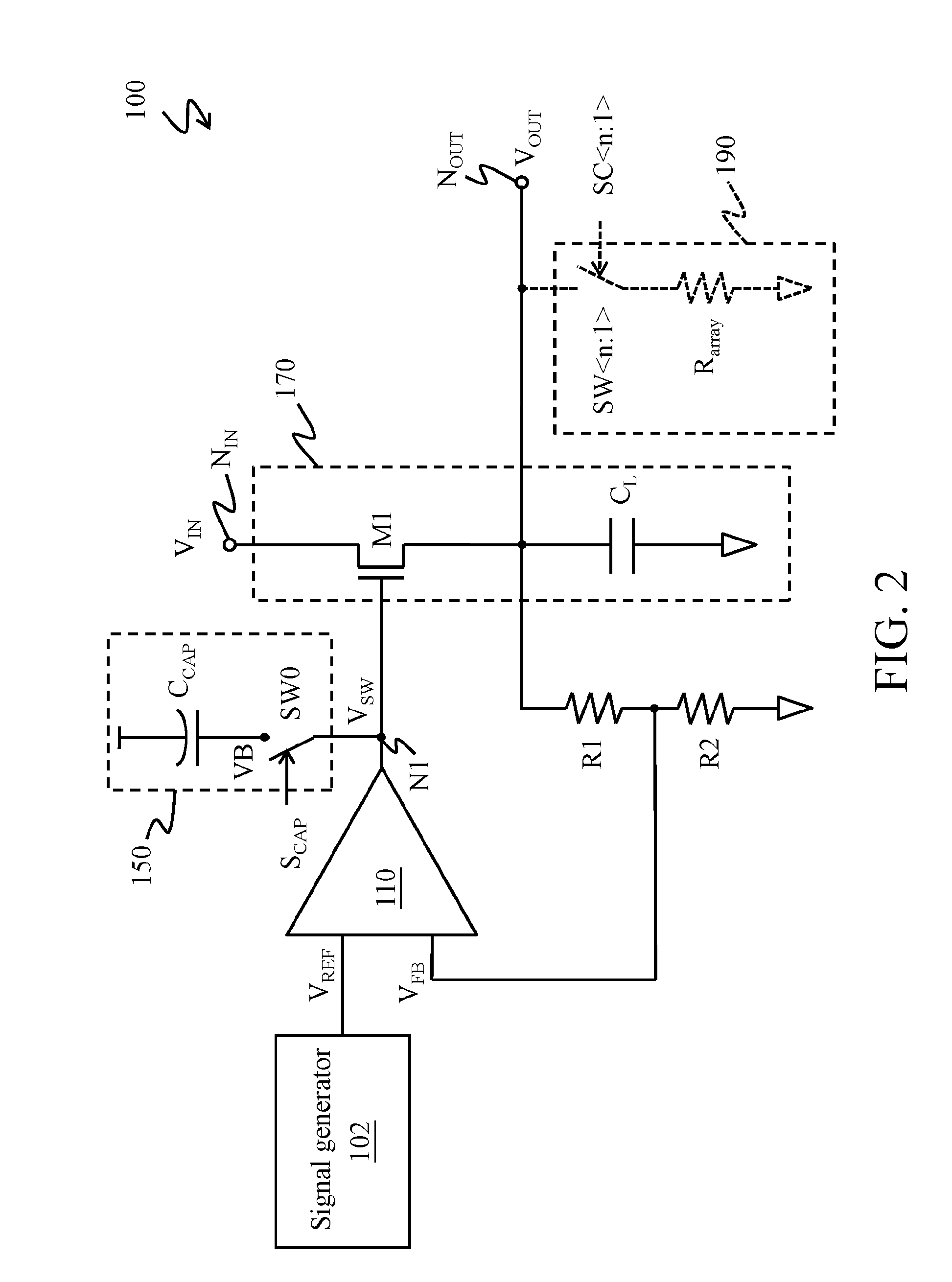
[0021]Referring to FIG. 1 and FIG. 2, a voltage regulating circuit 100 includes an error amplifier 110, a tank circuit 150, and an output circuit 170.

[0022]An output terminal of the error amplifier 110 is electrically connected to a control terminal of the output circuit 170 and the tank circuit 150 through a first contact N1. An input terminal of the output circuit 170 is electrically connected to a power contact NIN, and an output terminal of the output circuit 170 is electrically connected to a load contact NOUT.

[0023]A feedback path is provided between the load contact NOUT and a first input terminal of the error amplifier 110, so as to form a feedback loop. A second input terminal of the error amplifier 110 is electrically connected to a reference voltage VREF, and the reference voltage VREF is provided by a signal generator 102. The signal generator 102 may be an external component of the voltage regulating circuit 100 or an internal component of the voltage regulating circuit...


PUM


Abstract

A voltage regulating circuit and a method thereof are provided. The voltage regulating circuit includes: a tank circuit, an error amplifier, an output circuit, and a feedback circuit. The tank circuit provides a fixed voltage. The error amplifier generates an amplified voltage according to a reference voltage and a feedback voltage. The output circuit converts a supply voltage into an output voltage in response to at least one of the amplified voltage and the fixed voltage. The feedback circuit generates a feedback voltage according to the output voltage.

Description

CROSS-REFERENCES TO RELATED APPLICATIONS[0001]This non-provisional application claims priority under 35 U.S.C. §119(a) on Patent Application No. 201310359218.1 filed in China, P.R.C. on Aug. 16, 2013, the entire contents of which are hereby incorporated by reference.BACKGROUND[0002]1. Technical Field[0003]The present invention relates to a technology for providing a stable voltage, and in particular, to a voltage regulating circuit and a method thereof.[0004]2. Related Art[0005]A voltage regulator is a device for converting a supply voltage into a stable output voltage, and is generally disposed between a power supply and a load circuit. A good voltage regulator provides a stable output voltage, and is capable of stabilizing the output voltage rapidly when a load changes, so as to provide the load with a required load current. In most voltage regulators, an error amplifier is adopted to control an ON / OFF state of a power element according to a comparison result between a feedback vo...

Claims


Application Information

Patent Timeline
Patent Type & Authority Applications(United States)
IPC IPC(8): H04B1/04H02M1/08
CPCH04B1/04H04B2001/0433H02M1/08G05F1/56
Inventor ZHANG, BIN
Owner REALTEK SEMICON CORP
Why Eureka
Try Eureka