System, apparatus, and method for reducing inrush current in a transformer

a transformer and inrush current technology, applied in the field of transformer inrush current reduction, can solve the problems of reducing affecting the efficiency of transformers, so as to reduce the inrush current of transformers, reduce the inrush current of windings, and reduce the effect of inrush curren

Active Publication Date: 2015-02-12
SCHWEITZER ENGINEERING LABORATORIES
View PDF1 Cites 15 Cited by
  • Summary
  • Abstract
  • Description
  • Claims
  • Application Information

AI Technical Summary

Benefits of technology

The present disclosure is about reducing the inrush current in a three-phase power system. It provides a system, apparatus, and method to automatically establish residual flux levels in the transformer's core segments, which allows the transformer to be energized with reduced inrush current in the windings. This results in a reduced energy surge when the system is turned on, which can prolong the life of the system's components and lower maintenance costs.

Problems solved by technology

Such high transformer inrush currents have a number of potentially adverse effects.
For one, a high inrush current can significantly heat transformer windings and cause deterioration of insulation in the transformer.
In addition, high inrush currents can place large mechanical stresses on the transformer windings sufficient to displace the windings on the transformer core, which, in the worst case, can break electrical connections within the transformer.
Moreover, insulation compression from displacement of the transformer windings can result in turn-to-turn faults within the transformer, which, if left undetected, can eventually destroy the transformer.
Large inrush currents can also disrupt a power system by inappropriately tripping circuit breakers and over-current relays, by causing voltage sags which can affect sensitive equipment, by introducing large harmonic components, and by instigating sympathetic inrush currents in adjacent, parallel-connected transformers.
These prior methods have not been entirely satisfactory for use in power delivery systems because they have either required the temporary interposition of additional components in one of the circuits of the transformer during energization or have required circuit breakers capable of individual phase control with the possible need to measure residual flux levels in the transformer winding, which can be failure-prone or in some cases require significant upgrade of existing equipment.

Method used


Image

  • System, apparatus, and method for reducing inrush current in a transformer
  • System, apparatus, and method for reducing inrush current in a transformer
  • System, apparatus, and method for reducing inrush current in a transformer

Examples


Embodiment Construction

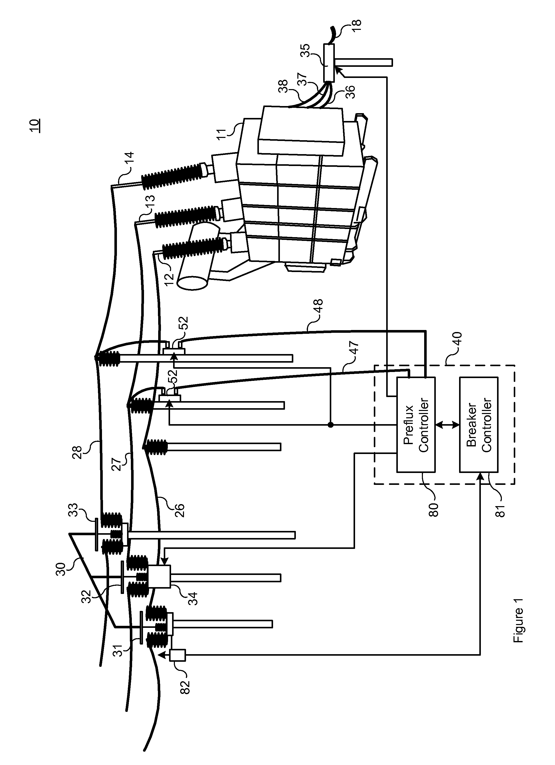
[0024]One method proposed by the present inventor for reducing inrush current in a single-phase transformer involves establishing a residual flux in the transformer core by means of a pre-fluxing circuit attached to one of the transformer's windings. The residual flux established in the transformer core approaches the prospective flux (the flux in the transformer core under steady state conditions) which will be produced when the winding is energized at a specific system voltage angle. As a consequence, inrush current to the pre-fluxed winding can be significantly reduced upon energization of the winding. The pre-fluxing device establishes the appropriate residual flux in the transformer core by supplying an appropriate amount of volt-seconds, also known as flux linkages, to the transformer core.

[0025]The system of the present disclosure reduces inrush current in a three-phase transformer by simultaneously establishing residual flux levels in each of the three core segments associat...


PUM


Abstract

A system for reducing inrush current in a three phase utility transformer upon energization of the transformer by an applied three phase voltage utilizes a pre-flux circuit for establishing residual flux levels in the core segments of the primary windings of the transformer which are near the prospective flux levels established in the core segments by the applied voltage. The pre-flux circuit includes a pre-fluxing capacitor which, after being charged to a predetermined voltage level, is discharged serially through two of the primary windings to establish the predetermined flux levels in the core segments of the two windings, and a reduced flux level in the core segment of the remaining primary winding. The transformer is energized at the instant of positively-referenced peak phase voltage to the third primary winding such that prospective and residual flux approach a near-equal level in all three core segments and inrush current is reduced. The method may be applied to the secondary or tertiary windings instead of the primary windings. Additionally, an alternative method allows application of the pre-fluxing circuit to a delta-connected set of transformer windings.

Description

CROSS-REFERENCE TO RELATED APPLICATIONS[0001]This application claims priority under 35 U.S.C. §120 as a continuation application of U.S. patent application Ser. No. 13 / 347,563 filed on 10 Jan. 2012 and titled “System, Apparatus, and Method for Reducing Inrush Current in a Three-Phase Transformer”, which is incorporated herein by reference.BACKGROUND OF THE INVENTION[0002]The present invention relates generally to transformer inrush current reduction, and more specifically, to a system, apparatus, and method for reducing inrush current when energizing a three-phase transformer.[0003]When energizing a three-phase transformer in an electric power delivery system (such as an electric power generation, transmission, or distribution system, or the like), inrush currents may occur which can be as large as ten times the transformer's nominal current and can last for up to around half of a second. The actual magnitude of these inrush currents depends on the impedance of the source supplying ...

Claims


Application Information

Patent Timeline
Patent Type & Authority Applications(United States)
IPC IPC(8): H02H7/04
CPCH02H7/04H02H9/002
Inventor TAYLOR, DOUGLAS I.
Owner SCHWEITZER ENGINEERING LABORATORIES
Why Eureka
Try Eureka