
Phase change material layers

Active Publication Date: 2015-02-12
SAMSUNG ELECTRONICS CO LTD
View PDF4 Cites 19 Cited by
  • Summary
  • Abstract
  • Description
  • Claims
  • Application Information

AI Technical Summary

Benefits of technology

This patent describes a way to make a layer of material that can change its phase to store and release heat. The method helps improve its ability to withstand high temperatures and to quickly crystallize when heated. This can be useful for creating highly stable and fast-reacting phase change memory devices.

Problems solved by technology

However, there may be a trade-off between the crystallization rate and a thermal stability of the phase change material layer.

Method used


Image

  • Phase change material layers
  • Phase change material layers
  • Phase change material layers

Examples


Embodiment Construction

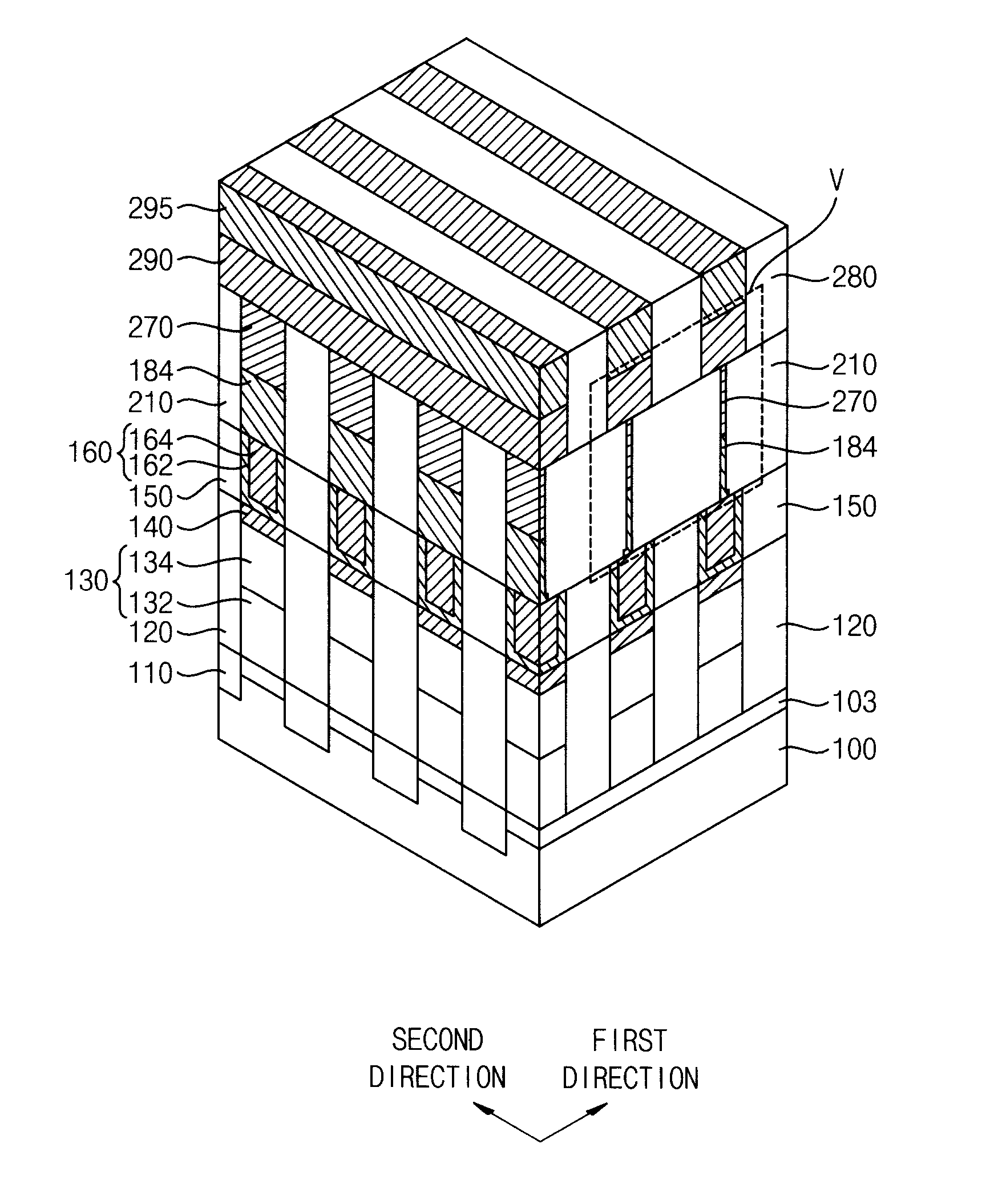
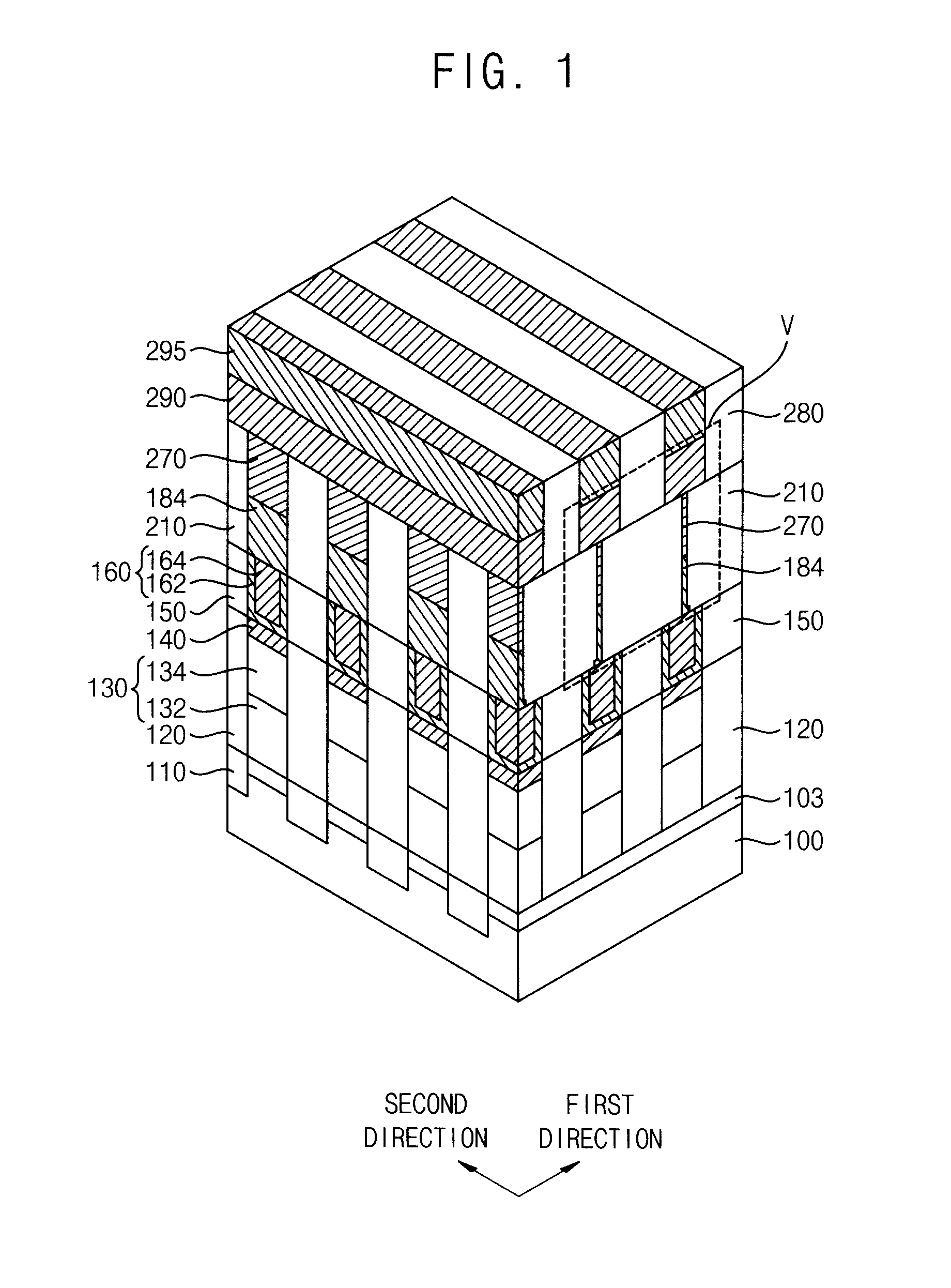
[0041]At least one example embodiment will now be described more fully with reference to the accompanying drawings, in which at least one example embodiment is shown. At least one example embodiment may, however, be embodied in many different forms and should not be construed as limited to the at least one example embodiment set forth herein. In the drawings, the thicknesses of layers and regions are exaggerated for clarity. Like reference numerals in the drawings denote like elements, and thus their description will be omitted.

[0042]It will be understood that when an element or layer is referred to as being “on,”“connected to” or “coupled to” another element or layer, it can be directly on, connected or coupled to the other element or layer or intervening elements or layers may be present. In contrast, when an element is referred to as being “directly on,”“directly connected to” or “directly coupled to” another element or layer, there are no intervening elements or layers present. ...


PUM

PropertyMeasurementUnit
Temperatureaaaaaaaaaa
Timeaaaaaaaaaa
Crystallization temperatureaaaaaaaaaa

Abstract

A phase change material layer includes germanium (Ge), antimony (Sb), tellurium (Te) and at least one impurity elements. An atomic concentration of impurity elements ranges from about 0<a≦about 0.25 and an atomic concentration of antimony (Sb) ranges from about 0.03<c≦about 0.15.

Description

CROSS-REFERENCE TO RELATED APPLICATION[0001]This application claims priority under 35 USC §119 to Korean Patent Application No. 10-2013-0092857, filed on Aug. 6, 2013 in the Korean Intellectual Property Office (KIPO), the contents of which are herein incorporated by reference in their entirety.BACKGROUND[0002]1. Field[0003]At least one example embodiment relates to phase change material layers and / or a method of manufacturing the same.[0004]2. Description of the Related Art[0005]A phase change memory device is a device for storing data using a resistance change generated by a phase transition between an amorphous state and a crystalline state of a phase change material layer pattern.[0006]During the operation of the phase change memory device, a current is applied to the phase change material layer, and a joule heat is generated in the phase change material layer. The joule heat may transform the phase change material layer to an amorphous state or to a crystalline state. That is, t...

Claims


Application Information

Patent Timeline
IPC IPC(8): H01L45/00
CPCH01L45/06H01L45/144H10B63/20H10B63/80H10N70/8265H10N70/231H10N70/828H10N70/8413H10N70/826H10N70/8828H10N70/023H10N70/066C23C16/305C30B29/46H10N70/882
Inventor KIM, DOHYUNG
Owner SAMSUNG ELECTRONICS CO LTD
Learn More