
Electro-hydraulic system for driving large-scale rotary motion valve supplied by solar low-capacity power

a solar and low-capacity power, electric-hydraulic technology, applied in the direction of valve operating means/release devices, machines/engines, mechanical equipment, etc., can solve the problems of system equipment cost, motion and maintenance costs to dramatically increase, system equipment cost to go up, etc., to improve the system input-output ratio and reduce the effect of equipment and motion maintenance costs

Inactive Publication Date: 2015-02-12
LIU BAOJUN
View PDF6 Cites 6 Cited by
  • Summary
  • Abstract
  • Description
  • Claims
  • Application Information

AI Technical Summary

Benefits of technology

The invention uses a small amount of solar power and a special motor to achieve its goals. This means that the device doesn't require a large starting current and can use a power supply that is not oversized. This reduces the cost of the device and improves its performance. The invention is also more eco-friendly because it uses less energy and produces less waste.

Problems solved by technology

Besides all above, to utilize AC power supply in the field needs to related electric transmission and transformation equipments, all these will result the system's equipment, motion and maintenance costs to dramatically go up.
If the large solar power supply is utilized to meet the system requirement this will also result the system's equipment cost to go up.

Method used


Image

  • Electro-hydraulic system for driving large-scale rotary motion valve supplied by solar low-capacity power
  • Electro-hydraulic system for driving large-scale rotary motion valve supplied by solar low-capacity power
  • Electro-hydraulic system for driving large-scale rotary motion valve supplied by solar low-capacity power

Examples


Embodiment Construction

[0011]Implementation example one: the linear motion to rotation motion conversion mechanism is rack and pinion.

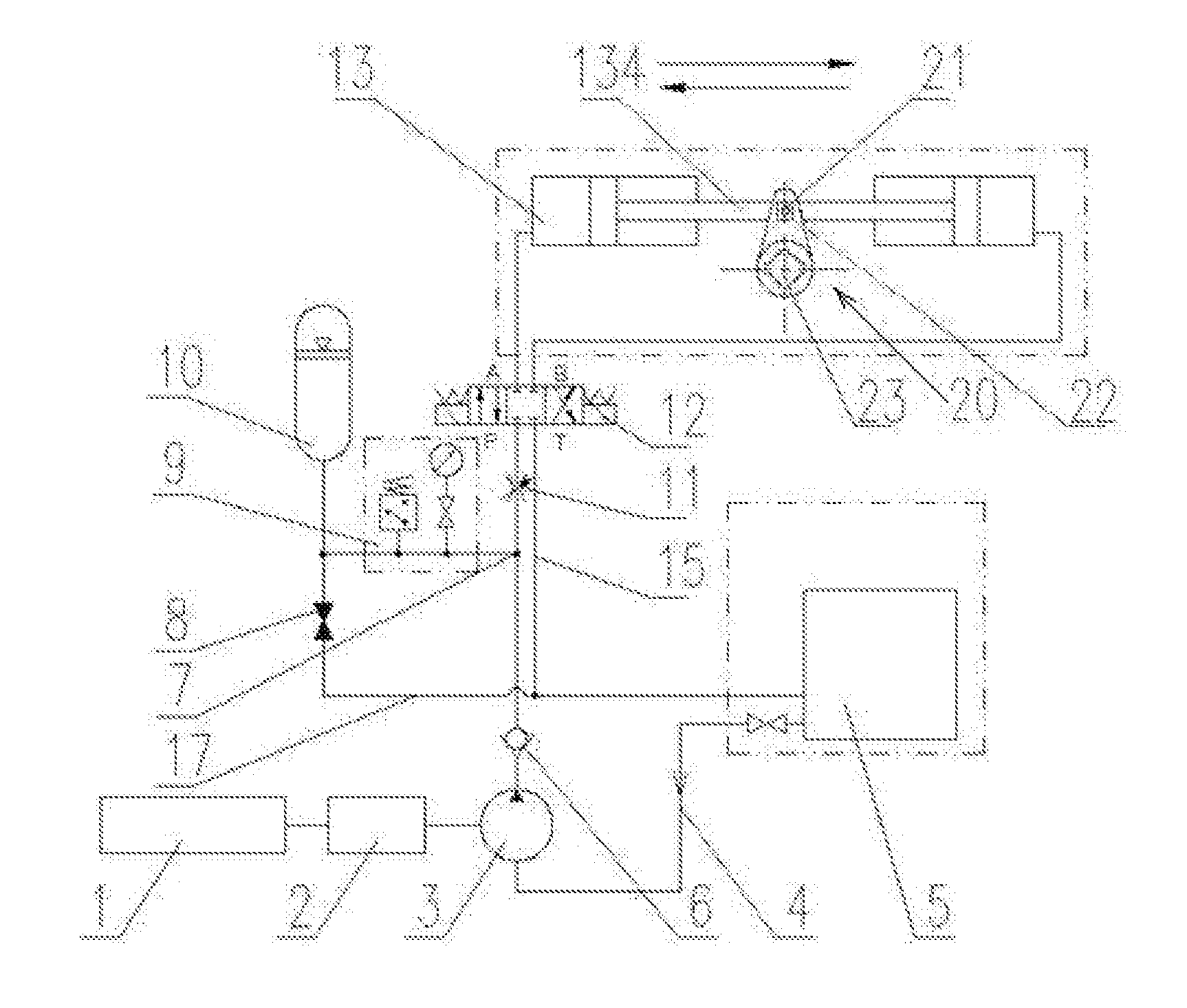
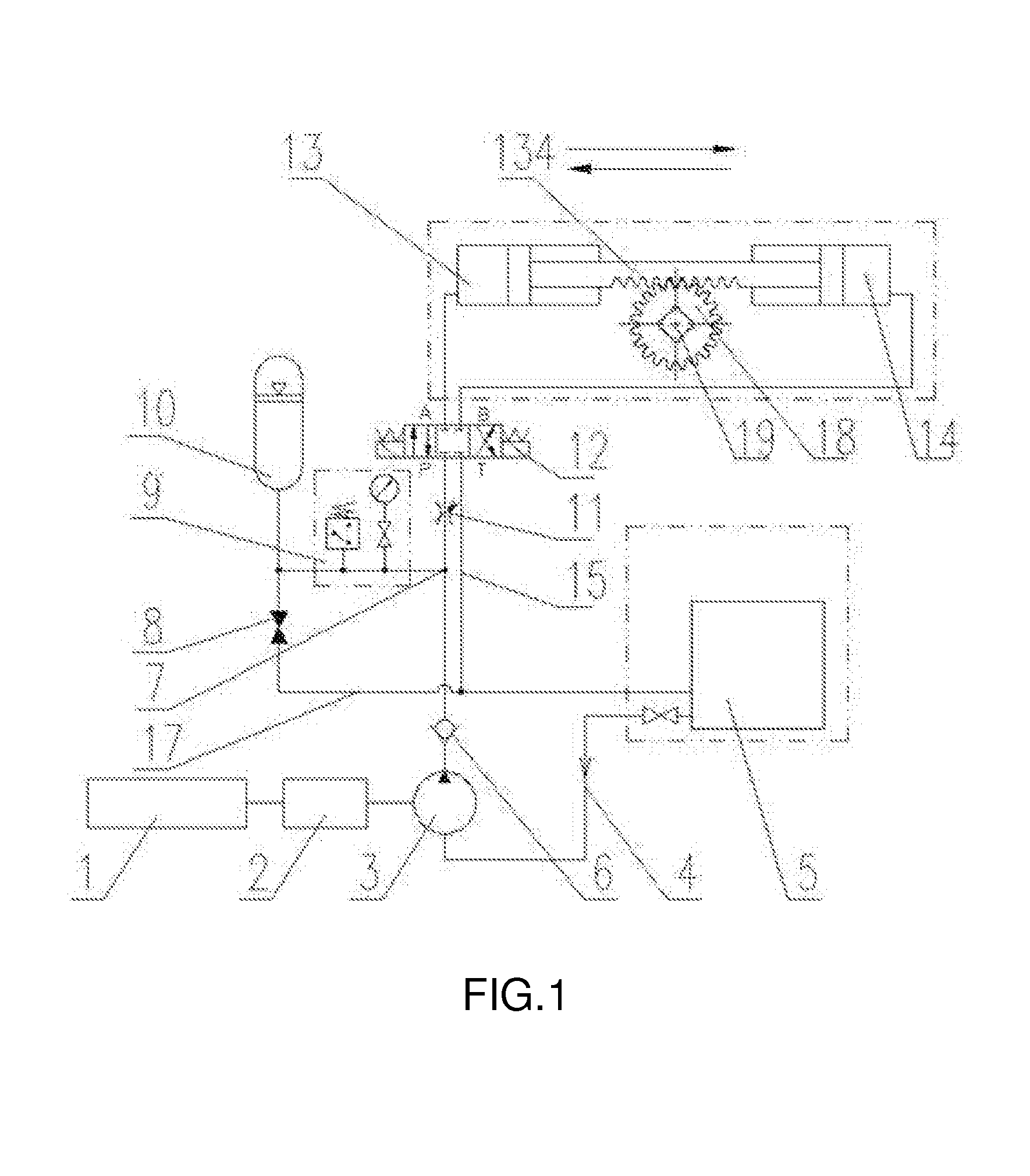
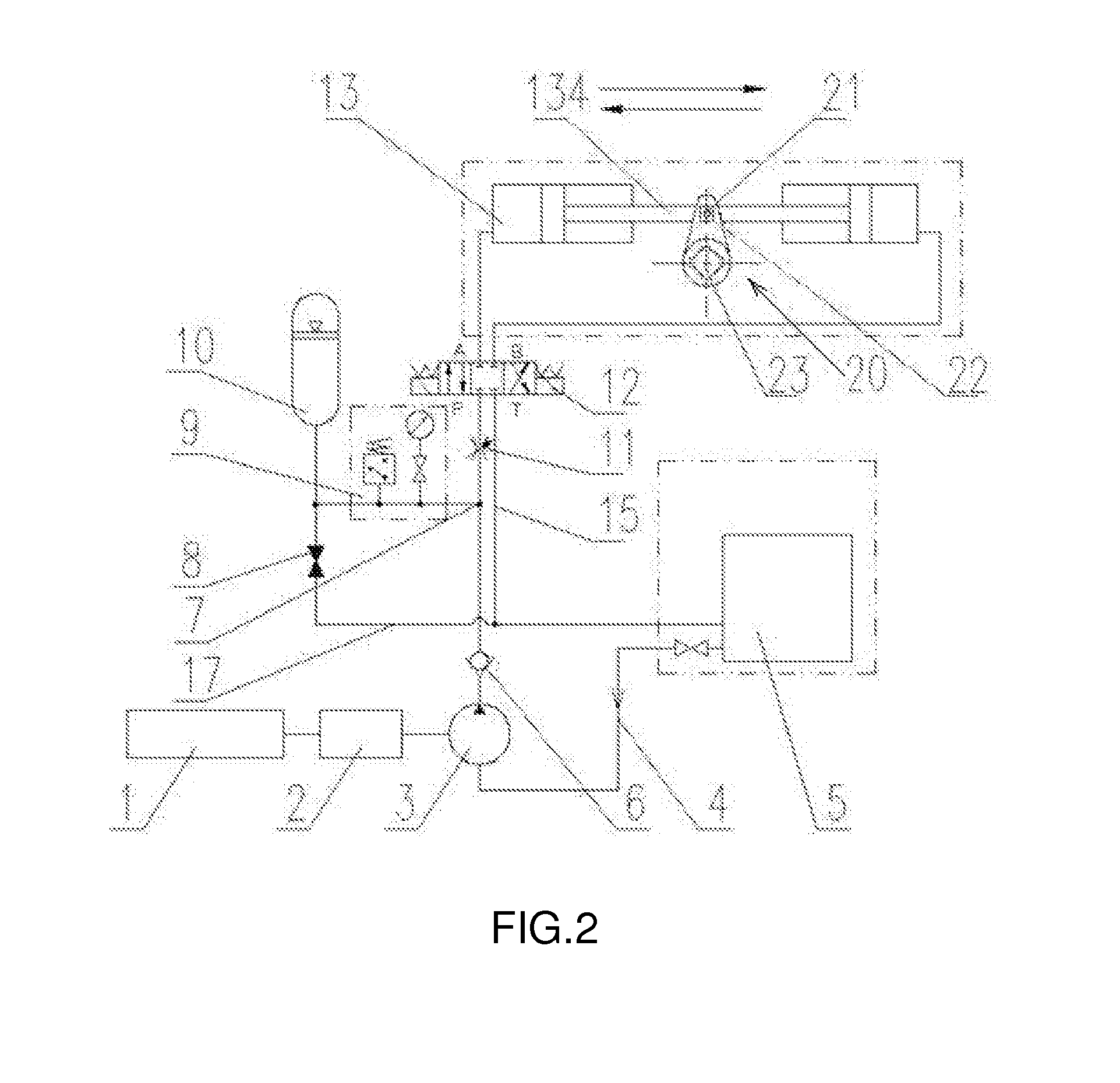
[0012]See FIG. 1. The 200˜500 W, 24VDC miniwatt solar power supply 1 drives stepper motor 2 and oil pump 3 in sequence. The oil storage pipeline 4 includes oil tank 5, oil pump, check valve 6, tee joint 7 and accumulator 10. The remaining port of tee joint connects with oil pumping pipeline 16; directional valve 12 oil inlet that is port P connects with oil pumping pipeline, the two ends of oil return pipeline 15 connect with directional valve's oil return port T and oil return port of the oil tank, the directional valve's A port connects with A cylinder 13 oil port, the directional valve's B port connects with B cylinder 14 oil port. A cylinder's and B cylinder's piston rod are connected by becoming one piston rod 134. The linear motion to rotation motion conversion mechanism between piston rod and rotary valve shaft is a rack and pinion design, one side of the piston rod ...


PUM


Abstract

An electro-hydraulic system for driving a large-scale rotary motion valve supplied by a solar low-capacity power. A step motor (2) and an oil pump (3) are in turn driven by a low-capacity solar power supply (1). An oil tank (5), the oil pump, a check valve (6), a T-connector (7) and a liquid accumulator (10) are in turn arranged on an oil storage pipeline (4). An oil inlet pipeline (16) is connected to the rest of the ports of the T-connector. An oil inlet of a three-position four-way reversing solenoid valve (12) is connected to the oil inlet pipeline. Two ends of an oil return pipeline are connected to an oil return port of the reversing valve and an oil return port of the oil tank, respectively. Each of two oil outlets of the reversing valve is respectively connected to an oil port of a single-chamber cylinder via a pipeline. The outer ends of the piston rods of cylinders A and B are rigidly connected together to form one piston rod (134). A linear-to-rotary transition mechanism is provided between the piston rod (134) and a spool (19) of the rotary motion valve. Since the low-capacity solar power supply is adopted in the system, the equipment cost, the operation cost and the maintenance cost of the system are reduced, and the input-output ratio of the system is increased.

Description

BACKGROUND OF THE INVENTION[0001]This invention refers to a type of Electro-hydraulic controlled driving system, specifically defined as t Miniwatt Solar Power supplied Electro-hydraulic System driving large rotary valve.[0002]The large rotary valves mentioned in this invention refers to valves, such as ball valve, butterfly valve, used in field oil or gas pipelines. The torque that drives the rotary valve is 500-110000N·m, equivalent to power output range of 500˜4000 W. Driving such large valves often requires large AC power supply, and the AC power supply and AC motor requires the starting current. Besides all above, to utilize AC power supply in the field needs to related electric transmission and transformation equipments, all these will result the system's equipment, motion and maintenance costs to dramatically go up. If the large solar power supply is utilized to meet the system requirement this will also result the system's equipment cost to go up.BRIEF SUMMARY OF THE INVENTI...

Claims


Application Information

Patent Timeline
IPC IPC(8): F16K31/163F16K31/54F16K31/42
CPCF16K31/1635F16K31/54F16K31/42F03G6/00F16K31/1225F16K31/52F24S2030/115Y02E10/46
Inventor LIU, BAOJUNZHENG, XUEMINGSHUN, XIANSHUANGLIU, GUANHUALEI, LINIE, QIANGXU, JINSHAN
Owner LIU BAOJUN
Learn More