
Safety device for battery pack having inserted-typed disconnect member

a safety device and battery pack technology, applied in the direction of secondary cell servicing/maintenance, safety/protection circuit, batteries, etc., can solve the problems of increasing manufacturing cost, complicated assembly process of such members, and modification of structure, so as to improve safety, easy to insert and separate, and easy inspection or replacement of circuit breaker units

Active Publication Date: 2015-02-05
LG ENERGY SOLUTION LTD
View PDF4 Cites 1 Cited by
  • Summary
  • Abstract
  • Description
  • Claims
  • Application Information

AI Technical Summary

Benefits of technology

The safety device for battery packs described in this patent is designed to easily insert and remove a circuit breaker unit, which can prevent damage to the battery if it malfunctions. The circuit breaker unit can be easily inspected or replaced, and it doesn't require an additional electrical connection process. The design also prevents disturbances caused by cables, making it safer. Overall, the safety device improves battery safety and allows for easy inspection and replacement of the circuit breaker unit.

Problems solved by technology

Particularly, in a case in which a plurality of battery modules is used to constitute the battery pack, a plurality of members, such as bus bars or power connection cables, for mechanical fastening and electrical connection between the battery modules is generally needed and, as a result, a process of assembling such members is very complicated.
Furthermore, in a case in which it is necessary to extend the battery pack, it is difficult to modify the structure of the battery pack and it is necessary to add a plurality of parts, thereby increasing manufacturing cost.
However, the provision of several sensors and a plurality of wires as well as the BMS increases manufacturing cost and complicates a manufacturing process.
For this reason, it is difficult to apply a large-sized breaker to a battery pack requiring high energy density.
For the fuse, on the other hand, it is difficult and troublesome to replace the fuse.
Specifically, in a case in which the fuse is mounted such that the fuse is exposed in order to easily replace the fuse, a short circuit with an adjacent electric power line may be caused.
In addition, an accident may occur due to an error in work during a process of separating and mounting the fuse in a structure in which a plurality of parts and cables is complexly arranged in the battery pack.
Furthermore, when a case having a fuse for safety disposed therein is used, it is difficult and troublesome to replace the fuse.

Method used


Image

  • Safety device for battery pack having inserted-typed disconnect member
  • Safety device for battery pack having inserted-typed disconnect member
  • Safety device for battery pack having inserted-typed disconnect member

Examples


Embodiment Construction

[0037]Now, exemplary embodiments of the present invention will be described in detail with reference to the accompanying drawings. It should be noted, however, that the scope of the present invention is not limited by the illustrated embodiments.

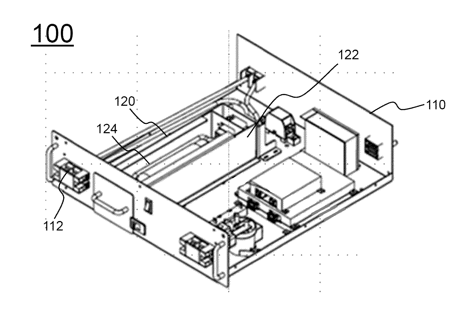
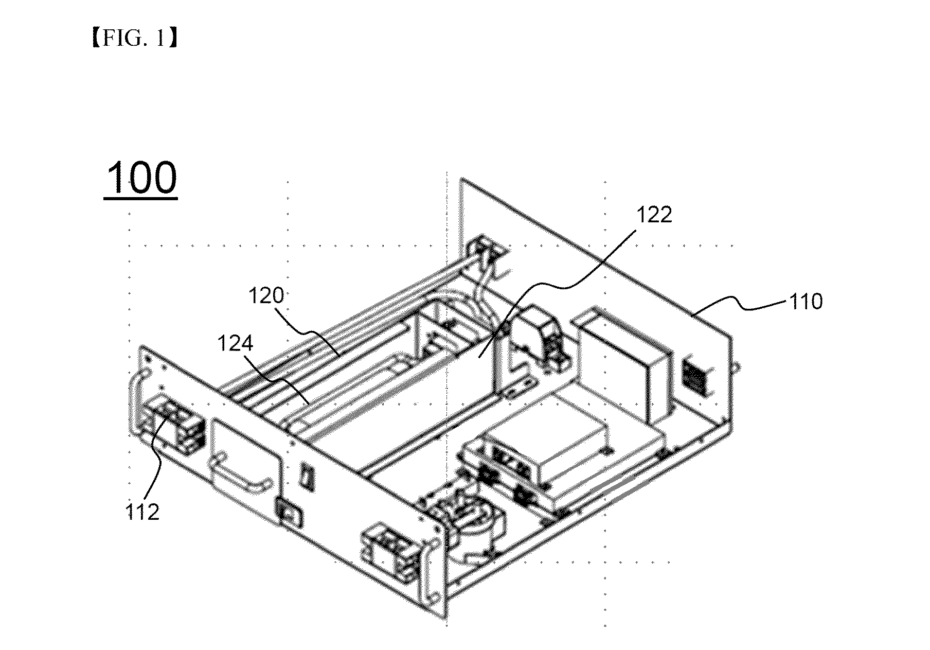
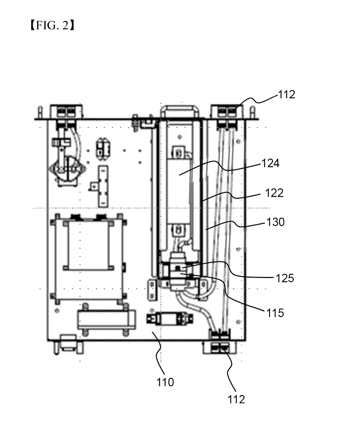
[0038]FIG. 1 is a perspective view showing a safety device for battery packs according to an embodiment of the present invention and FIG. 2 is a plan view of the safety device for battery packs shown in FIG. 1.

[0039]Referring to FIGS. 1 and 2, a safety device 100 for battery packs includes a safety device case I 10 and a circuit breaker unit 120. The safety device case 110 is provided with a connection terminal 112 connected to a main cable of a battery pack (not shown), in which the safety device 100 is mounted. The circuit breaker unit 120 is mounted into the safety device case 110 in an insertion fashion. The circuit breaker unit 120 is electrically connected to the connection terminal 112 in a state in which the circuit breaker unit 120 ...


PUM

PropertyMeasurementUnit
electric currentaaaaaaaaaa
electric poweraaaaaaaaaa
energy efficiencyaaaaaaaaaa

Abstract

Disclosed herein is a safety device mounted in a battery pack including one or more battery modules, each of which includes a plurality of unit modules electrically connected to each other, to interrupt a flow of electric current in the battery pack in an abnormal state of the battery pack, the safety device including a safety device case provided with a connection terminal connected to a main cable of the battery pack and a circuit breaker unit mounted into the safety device case from an outside of the battery pack in an insertion fashion such that the circuit breaker unit is electrically connected to the connection terminal in a state in which the circuit breaker unit is mounted in the safety device case and the circuit breaker unit is electrically disconnected from the connection terminal in a state in which the circuit breaker unit is separated from the safety device case.

Description

TECHNICAL FIELD[0001]The present invention relates to a safety device for battery packs including an insertion type circuit breaker unit.BACKGROUND ART[0002]Recently, a secondary battery, which can be charged and discharged, has been widely used as an energy source for wireless mobile devices. In addition, the secondary battery has attracted considerable attention as a power source for electric vehicles (EV), hybrid electric vehicles (NEV), and plug-in hybrid electric vehicles (Plug-in HEV), which have been developed to solve problems, such as air pollution, caused by existing gasoline and diesel vehicles using fossil fuels.[0003]In addition, technology related to a power storage device that stores electric power and stably supplies the stored electric power to a power system when needed has been developed. The power storage device is a device that stores electric power when power demand is low and supplies the stored electric power in case of overload or emergency. The power storag...

Claims


Application Information

Patent Timeline
Patent Type & Authority Applications(United States)
IPC IPC(8): H02J7/00H01M10/42
CPCH02J7/0031H01M2010/4271H01M10/425H01M10/4207H01H2085/025H01M2200/00H01H85/22Y02E60/10H01M2200/103H01M50/572
Inventor KIM, TAEYEOP
Owner LG ENERGY SOLUTION LTD
Learn More