Electric vehicle

Inactive Publication Date: 2015-02-05
TOYOTA JIDOSHA KK
View PDF2 Cites 28 Cited by
  • Summary
  • Abstract
  • Description
  • Claims
  • Application Information

AI Technical Summary

Benefits of technology

The present patent provides a technique for effectively and efficiently using a PTC thermistor to discharge a capacitor while suppressing heat generation of the discharge resistor. This technique can be utilized in an electric vehicle to rapidly discharge the capacitor in case of a collision or other emergency situations. This technique also allows for a gradual discharge over a longer period of time. A discharge controller is provided to protect the discharge circuit from overheating. Overall, this patent aims to provide a cost-effective and size-efficient solution for discharging a capacitor in electric vehicles.

Problems solved by technology

It is not desirable for a large amount of charge to remain in the capacitor after a main switch (ignition switch) of the vehicle has been turned OFF, or in an unexpected event, such as an accident, etc.
However, providing a large discharge resistor is not desirable from the point of view of cost and compactness.

Method used


Image

  • Electric vehicle
  • Electric vehicle
  • Electric vehicle

Examples


first embodiment

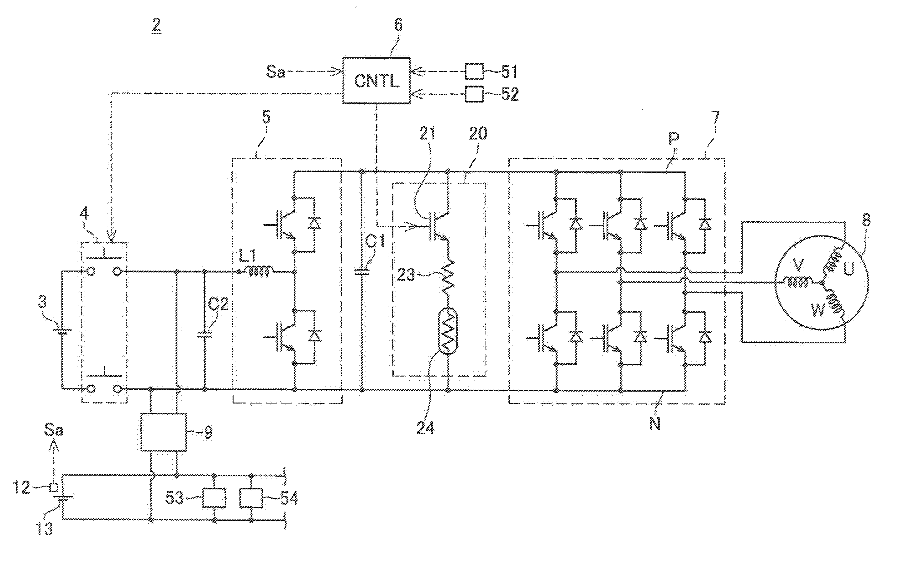
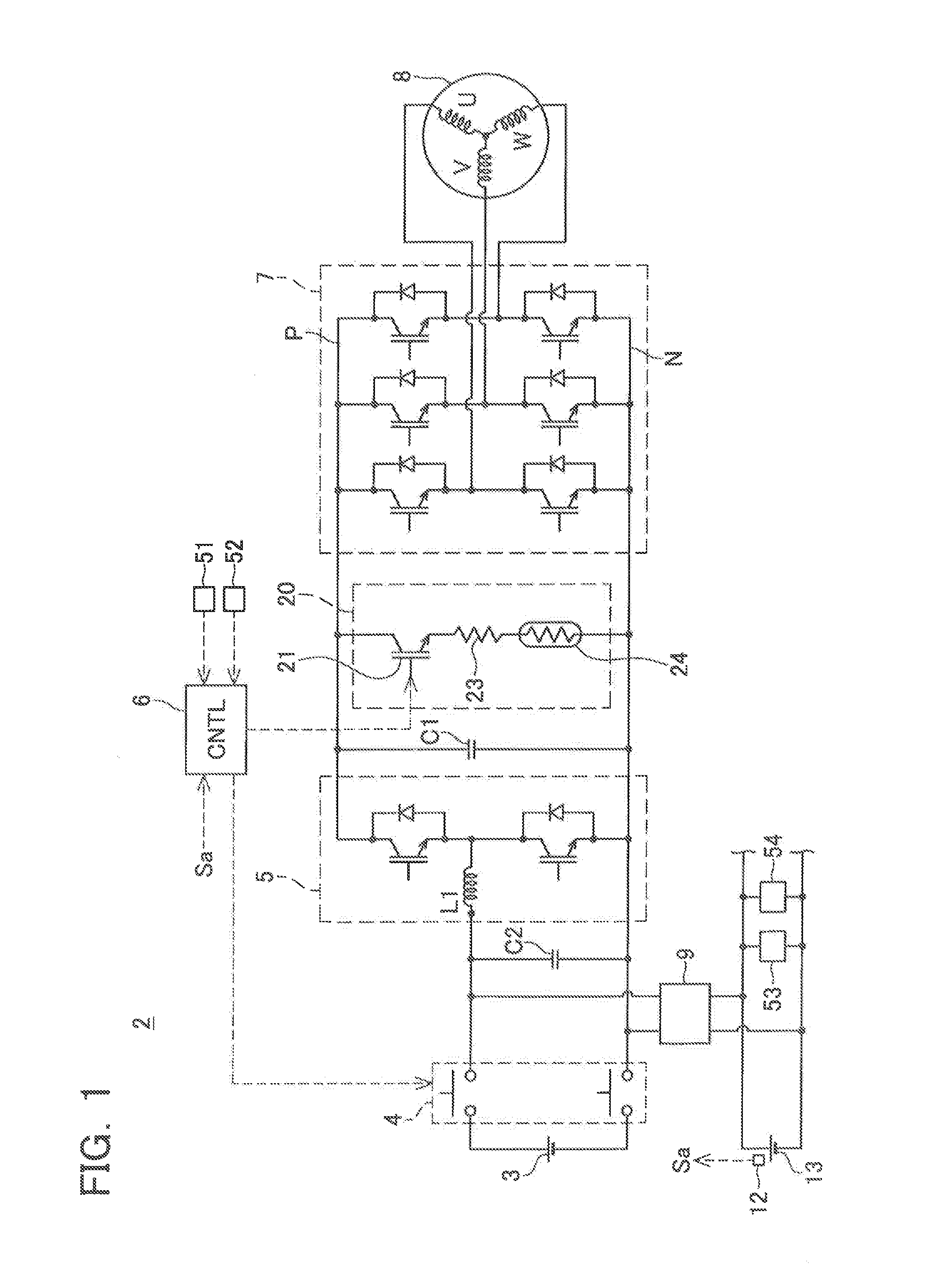
[0028]An electric vehicle of a first embodiment will be described. The electric vehicle of the first embodiment is a hybrid vehicle 2 comprising both an engine and a motor for driving, FIG. 1 shows a block diagram of a power system of the hybrid vehicle 2. In FIG. 1, the engine is not shown. Further, it should be noted that only components needed for the description of the present specification are depicted in FIG. 1, and devices not related to the description are not shown even if the devices belong to the power system.

[0029]Power for driving a motor 8 is supplied from a main battery 3. The output voltage of the main battery 3 is, e.g., 300 volts. Moreover, in addition to the main battery 3, the hybrid vehicle 2 also comprises an auxiliary battery 13 for supplying power to devices (often called “auxiliaries”) such as a car navigation system 53, an interior light 54, etc., which are driven by a voltage lower than the output voltage of the main battery 3. The output voltage of the au...

second embodiment

[0047]FIG. 4 shows a block diagram of a hybrid vehicle 2a of a second embodiment. In the hybrid vehicle 2a, the configuration of a discharge circuit 20a differs from the first embodiment. The configuration other than the discharge circuit 20a is the same as the first embodiment, and consequently a description thereof is omitted.

[0048]The discharge circuit 20a comprises a second resistor 25 in addition to the configuration of the discharge circuit 20 of the first embodiment. The second resistor 25 is connected to the semiconductor switch 21 and the first resistor 23 in series. Further, the second resistor 25 is connected to the PTC thermistor 24 in parallel. According to this configuration, electric current flows through the series circuit configured by the first resistor 23 and the PTC thermistor 24 while the temperature of the PTC thermistor 24 is low. When the temperature of the PTC thermistor 24 increases, the electric current flows through the series circuit configured by the fi...

third embodiment

[0050]Next, an electric vehicle of a third embodiment will be described. FIG. 5 shows a block diagram of a hybrid vehicle 2b of a third embodiment. In the hybrid vehicle 2b, the configuration of a. discharge circuit 20b differs from the first embodiment. The configuration other than the discharge circuit 20b is the same as the first embodiment, and consequently a description thereof is omitted. The discharge circuit 20b comprises a third resistor 26 in addition to the configuration of the discharge circuit 20 of the first embodiment, The third resistor 26 is connected in parallel to a series circuit which is configured by the semiconductor switch 21, the first resistor 23 and the PTC thermistor 24. That is, the third resistor 26 is constantly connected to the capacitor C1 in parallel. The resistance value of the third resistor 26 is selected to be a value higher than the resistance value of the first resistor 23. The discharge circuit 20b of the third embodiment discharges the capac...


PUM


Abstract

An electric vehicle is provided, which includes a circuit for discharging a capacitor which smoothes electric current of a power converter. A hybrid vehicle includes a capacitor for smoothing electric current, a discharge circuit, and a discharge controller. The discharge circuit is connected to the capacitor in parallel. The discharge circuit includes a series circuit configured by a first resistor, a PTC thermistor, and a switch. When the discharge controller closes the switch, electric current starts to flow through the first resistor and the PTC thermistor. The capacitor is discharged rapidly. When continuing inflow of electric current to the discharge circuit is more than envisaged, the temperature rises due to heat generation by the PTC thermistor itself, and resistance increases. Thereupon, the electric current flowing into the first resistor is suppressed, suppressing heat generation of the first resistor.

Description

TECHNICAL FIELD[0001]The present specification relates to an electric vehicle. Specifically, the present specification relates to a technique for discharging a capacitor for smoothing an electric current in a motor power supply system of an electric vehicle. “Electric vehicle” in the present specification includes a vehicle equipped with a fuel cell, and a hybrid vehicle provided with a motor and engine.BACKGROUND ART[0002]The rated output of a motor of an electric vehicle is several tens of kilowatts, and a large electric current is required. On the other hand, a motor power supply system is often provided with a capacitor for smoothing pulsations of electric current. Typically, the smoothing capacitor is connected in parallel to an inverter, a voltage converter, etc. A capacitor with a large capacity is utilized for smoothing the large electric current supplied to the motor. Below, the smoothing capacitor will be referred to simply as capacitor. Further, in the present specificati...

Claims


Application Information

Patent Timeline
IPC IPC(8): B60L3/04H02J7/00
CPCH02J7/0029B60L3/04B60L3/0046B60L7/14B60L15/007B60L2210/10B60L2240/36B60L2270/20B60L50/51B60L58/20B60L58/24B60L58/40B60L58/13B60L58/14Y02T10/64Y02T10/70Y02T10/72H02M1/322
Inventor HIROSE, KENTARO
Owner TOYOTA JIDOSHA KK
Why Eureka
Try Eureka