Film forming process and film forming apparatus
- Summary
- Abstract
- Description
- Claims
- Application Information
AI Technical Summary
Benefits of technology
Problems solved by technology
Method used
Image

Examples
first exemplary embodiment
Effect of First Exemplary Embodiment
[0134]According to the first exemplary embodiment, the film forming apparatus 10 performs an adsorption step in which a precursor gas chemically adsorbed on the surface of a substrate mounted on a mounting table provided within a hermetically sealed processing container. The film forming apparatus 10 performs a first reaction step in which a reaction gas is supplied into the processing container to generate plasma of the reaction gas, and the plasma of the reaction gas is reacted with the surface of the substrate. The film forming apparatus 10 performs a second reaction step in which a modifier gas, which is any gas of an ammonia gas, an argon gas, a nitrogen gas, and a hydrogen gas, or a mixed gas obtained by mixing these gases, is supplied into the processing container, generating plasma of the modifier gas, and the plasma of the modifier gas is reacted with the surface of the substrate. Accordingly, a throughput of producing a nitride film on t...
second exemplary embodiment
Effect of Second Exemplary Embodiment
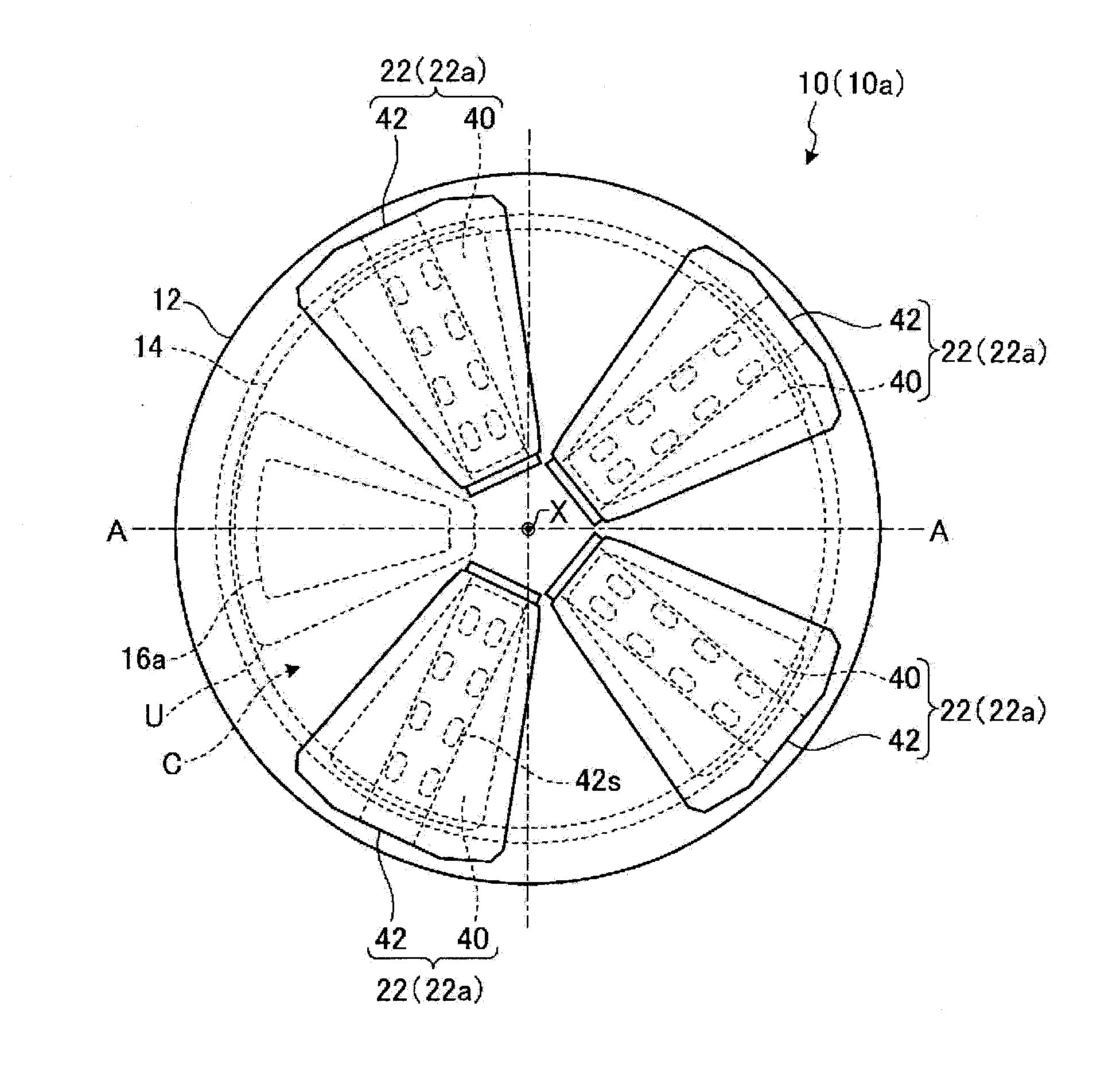
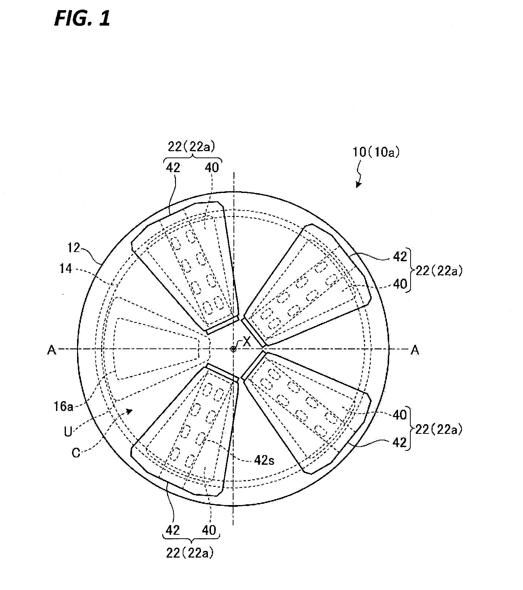
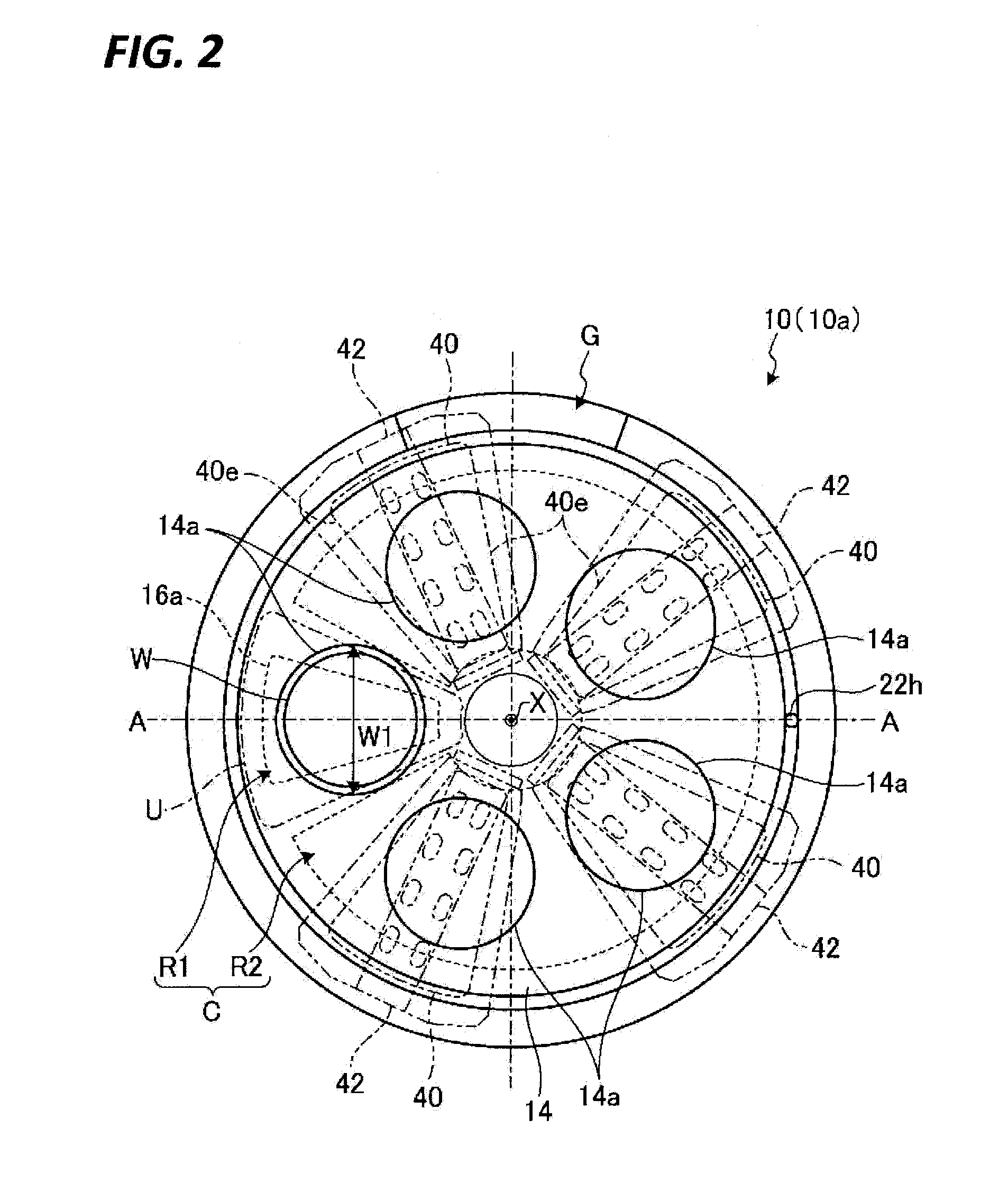
[0151]According to the second exemplary embodiment as described above, the film forming apparatus 10a performs an adsorption step in which a precursor gas is adsorbed on the surface of a substrate mounted on a mounting table provided within a hermetically sealed processing container. The film forming apparatus 10a performs a first reaction step in which a reaction gas is supplied into the processing container to generate plasma of the reaction gas, and the plasma of the reaction gas is reacted with the surface of the substrate. The film forming apparatus 10a performs a second reaction step in which an argon gas and a nitrogen gas are supplied into the processing container, ions or radicals of the modifier gas are generated by plasma, and the plasma of the modifier gas is reacted with the surface of the substrate. The film forming apparatus 10a sequentially and repeatedly performs a series of treatments of the adsorption step, the first reaction s...
third exemplary embodiment
Effect of Third Exemplary Embodiment
[0178]According to the third exemplary embodiment, through a relatively simple configuration of the film forming apparatus 100, the film quality of a nitride film may be efficiently improved, and the film thickness of the nitride film may be secured. That is, it is possible to improve both the throughput of film forming and the film quality.
Fourth Exemplary Embodiment
[0179]The fourth exemplary embodiment has the same as the third exemplary embodiment in configuration of a film forming apparatus. The fourth exemplary embodiment is different from the third exemplary embodiment in that in a film forming process, a DCS adsorption pre-treatment to be described later is performed prior to the DCS adsorption treatment to be described below. Hereinafter, a film forming process by a film forming apparatus according to the fourth exemplary embodiment will be described. The film forming apparatus according to the fourth exemplary embodiment is referred to as...
PUM
| Property | Measurement | Unit |
|---|---|---|
| Thickness | aaaaa | aaaaa |
| Adsorption entropy | aaaaa | aaaaa |
Abstract
Description
Claims
Application Information
 - R&D
- Intellectual Property
- Life Sciences
- Materials
- Tech Scout
- Unparalleled Data Quality
- Higher Quality Content
- 60% Fewer Hallucinations
Browse by: Latest US Patents, China's latest patents, Technical Efficacy Thesaurus, Application Domain, Technology Topic, Popular Technical Reports.
© 2025 PatSnap. All rights reserved.Legal|Privacy policy|Modern Slavery Act Transparency Statement|Sitemap|About US| Contact US: help@patsnap.com