
Multicast routing protocol for computer networks

a routing protocol and computer network technology, applied in the field of routing protocols, can solve the problems of routers so busy, other communications (i.e., other than), delay in communication, etc., and achieve the effect of reducing the scope of travel of the first packet, reducing the number of prune packets generated, and reducing the number of duplicate packets

Active Publication Date: 2015-01-29
SOUTHERN ILLINOIS UNIVERSITY
View PDF4 Cites 10 Cited by
  • Summary
  • Abstract
  • Description
  • Claims
  • Application Information

AI Technical Summary

Benefits of technology

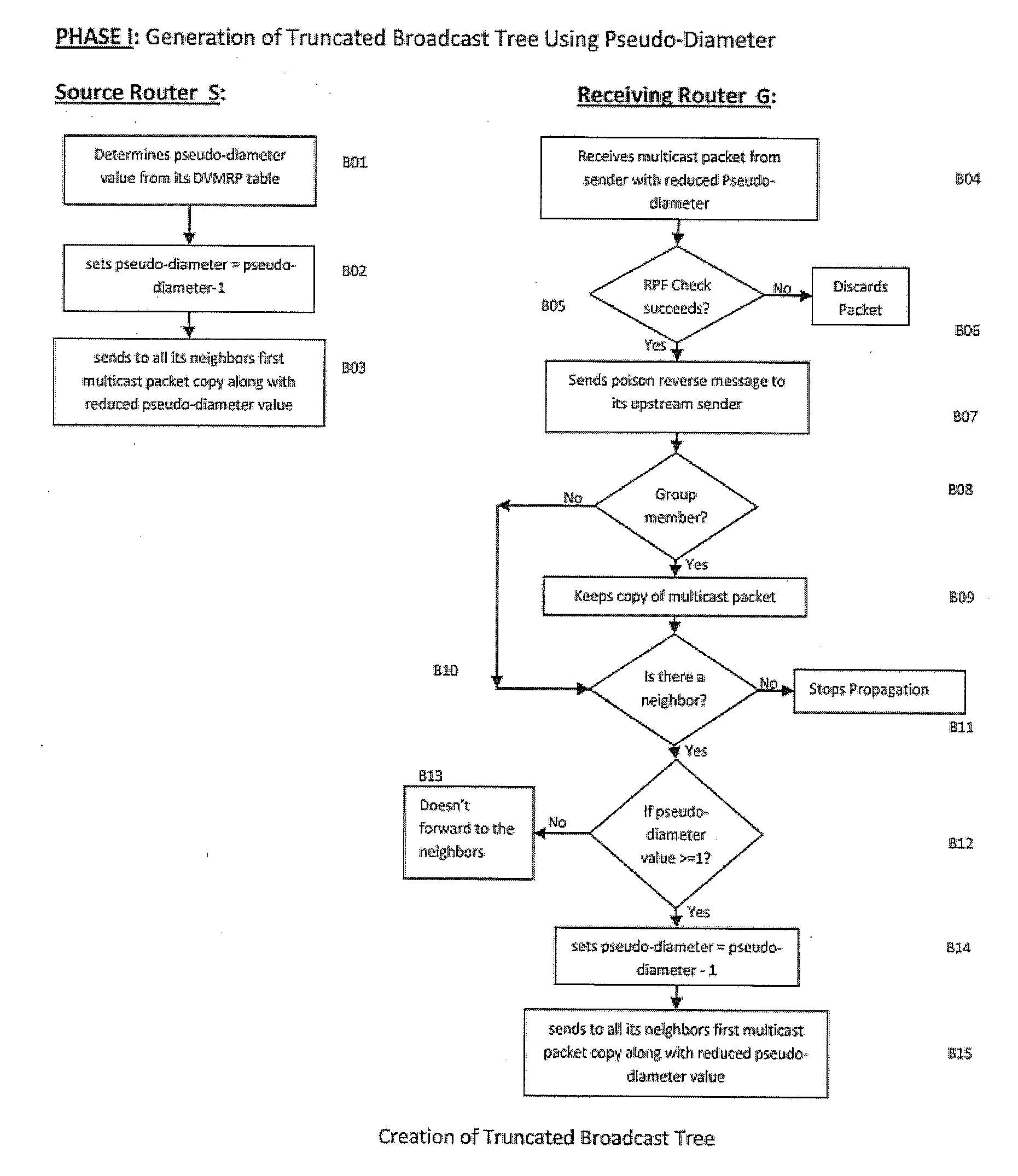
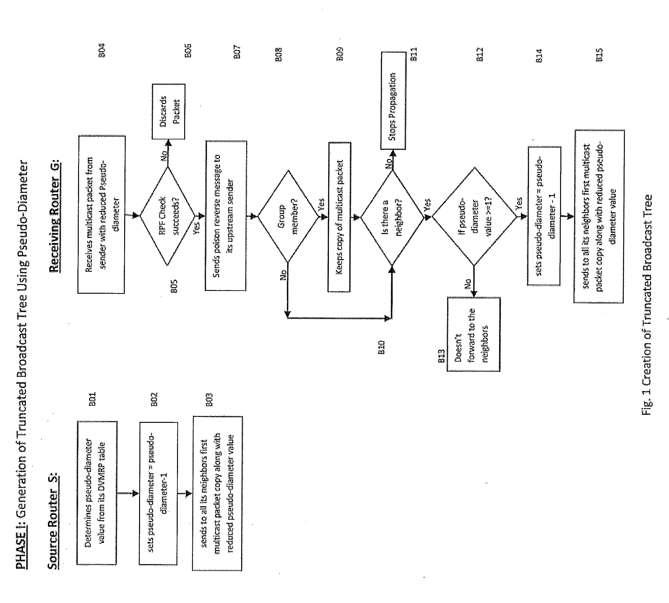
The patent proposes a method and system to improve efficiency in multicast network communication. It suggests using the pseudo-diameter of a multicast source to control packet propagation during broadcasting, instead of using the domain diameter. This reduces the number of duplicate packets generated during broadcasting and prune packets, which helps avoid unnecessary traffic in the network. By incorporating this location aspect in packet forwarding, the technology achieves improved bandwidth utilization, especially in cases where many concurrent multicast sessions take place in the same network.

Problems solved by technology

This process has been described as ‘routing by rumor’ because routers are relying on the information they receive from other routers and cannot determine if the information is actually valid and true.
For its proper implementation, it generates a very large number of control packets, known as prune packets; these prune packets consume a considerable amount of network bandwidth, which results in slower traffic movement in the networks causing delay in communication.
Since transmissions of these packets have to be done by routers, it keeps routers so busy that other communications (i.e., other than multicasting) such as email, file transfer, web browsing etc. which need these routers are affected and get delayed.
It may also affect the speed at which an urgent multicast session must complete.
In reality thousands of multicasting sessions take place at any given time and therefore in general the overall traffic-load situation is extremely bad from the viewpoint of communication delay and congestion when DVMRP is used.

Method used


Image

  • Multicast routing protocol for computer networks
  • Multicast routing protocol for computer networks
  • Multicast routing protocol for computer networks

Examples


Embodiment Construction

[0039]According to the embodiment(s) of the present invention, various views are illustrated in FIG. 1-18 and like reference numerals are being used consistently throughout to refer to like and corresponding parts of the invention for all of the various views and figures of the drawing. Also, please note that the first digit(s) of the reference number for a given item or part of the invention should correspond to the Fig. number in which the item or part is first identified.

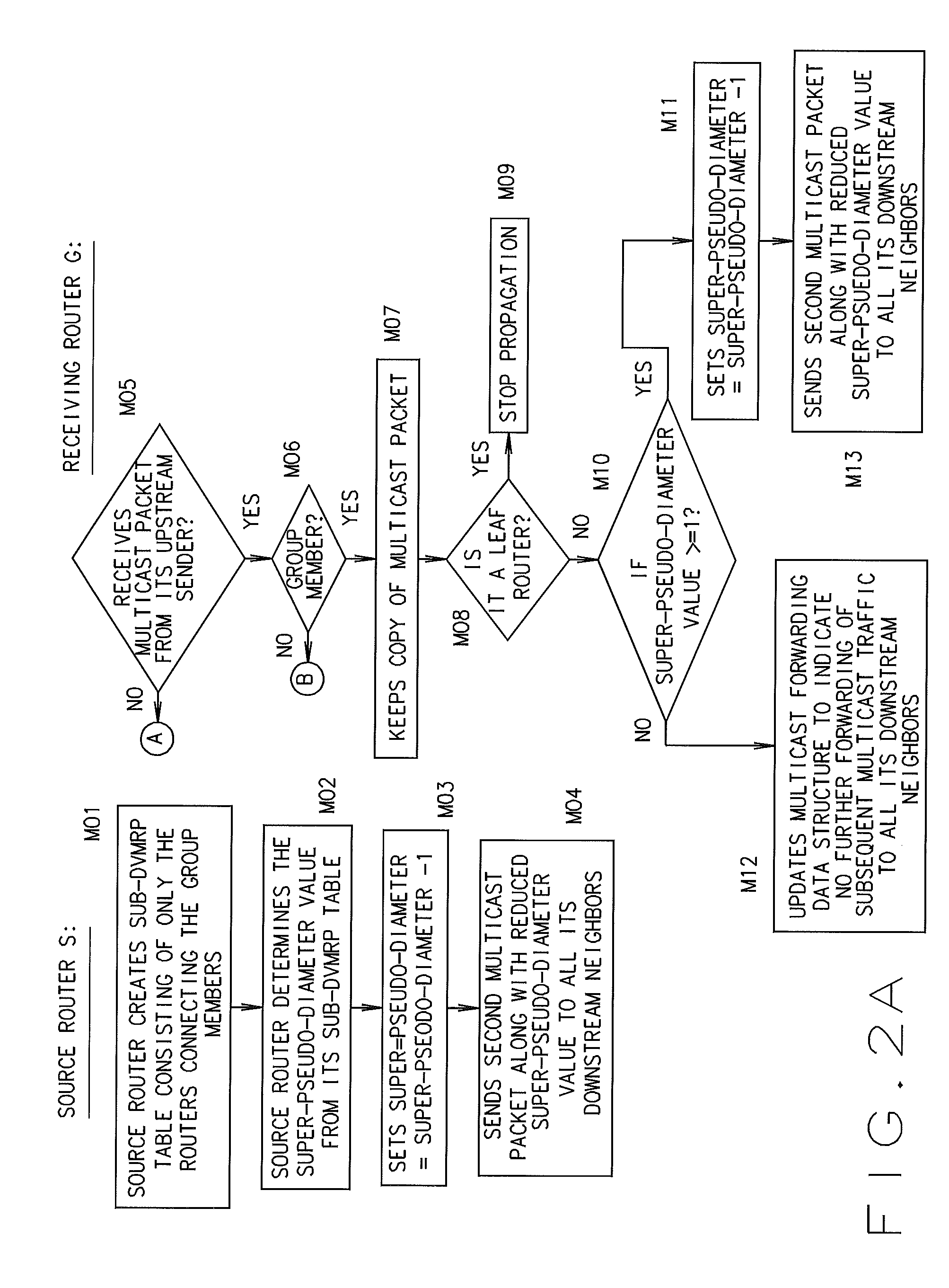
[0040]One embodiment of the present technology comprising a method and apparatus for a routing protocol for a router teaches a novel apparatus and method for distance vector multicasting routing. The method and apparatus as disclosed and claimed offers a very meaningful and important new interpretation of the routing information stored in a DVMRP routing table. This interpretation relates to the knowledge of the locations of a multicast source router and the routers connected to hosts with group members in a DVMR...


PUM


Abstract

The present technology comprises a method and apparatus for a routing protocol for a router including an apparatus and method for distance vector multicast routing. The method and apparatus as disclosed and claimed offers a new interpretation of the routing information stored in a DVMRP routing table. This interpretation relates to the knowledge of the locations of a multicast source router and the routers connected to hosts with group members in a DVMRP domain. The methodology exploits this knowledge to create two conditional packet forwarding checks, based on pseudo-diameter and super-pseudo-diameter respectively, and used these conditions to extend the two phases of the existing DVMRP to improve its performance from the viewpoint of much better utilization of bandwidth.

Description

CROSS REFERENCE[0001]This application claims priority to and the benefit of U.S. Provisional Patent Application Ser. No. 61 / 858,409 entitled Multicast Routing Protocol For Computer Networks filed Jul. 25, 2013, which is hereby incorporated by reference in its entirety.BACKGROUND[0002]1. Field[0003]This technology relates generally to routing protocol and, more particularly, to routing protocol for computer networks.[0004]2. Background Art[0005]In computer communication theory relating to packet-switched networks, a distance-vector routing protocol is one of the two major classes of routing protocols, the other major class being the link-state protocol. Distance-vector routing protocols use the Bellman-Ford algorithm, Ford-Fulkerson algorithm to calculate paths. A distance-vector routing protocol requires that a router informs its neighbours of topology changes periodically. Compared to link-state protocols, which require a router to inform all the nodes in a network of topology chan...

Claims


Application Information

Patent Timeline
Patent Type & Authority Applications(United States)
IPC IPC(8): H04L12/18H04L12/753H04L45/122H04L45/16
CPCH04L45/48H04L12/18H04L45/20H04L45/16
Inventor GUPTA, BIDYUTKONERU, SINDOORARAHIMI, SHAHRAM
Owner SOUTHERN ILLINOIS UNIVERSITY
Learn More