
Common mode filter

a filter and common mode technology, applied in the direction of inductance, fixed capacitor details, emergency protective arrangements for limiting excess voltage/current, etc., can solve the problems of difficult implementation of thinned chips, signal distortion due to high-frequency noise, etc., and achieve the effect of easy implementation of thin chips

Active Publication Date: 2015-01-29
SAMSUNG ELECTRO MECHANICS CO LTD
View PDF4 Cites 9 Cited by
  • Summary
  • Abstract
  • Description
  • Claims
  • Application Information

AI Technical Summary

Benefits of technology

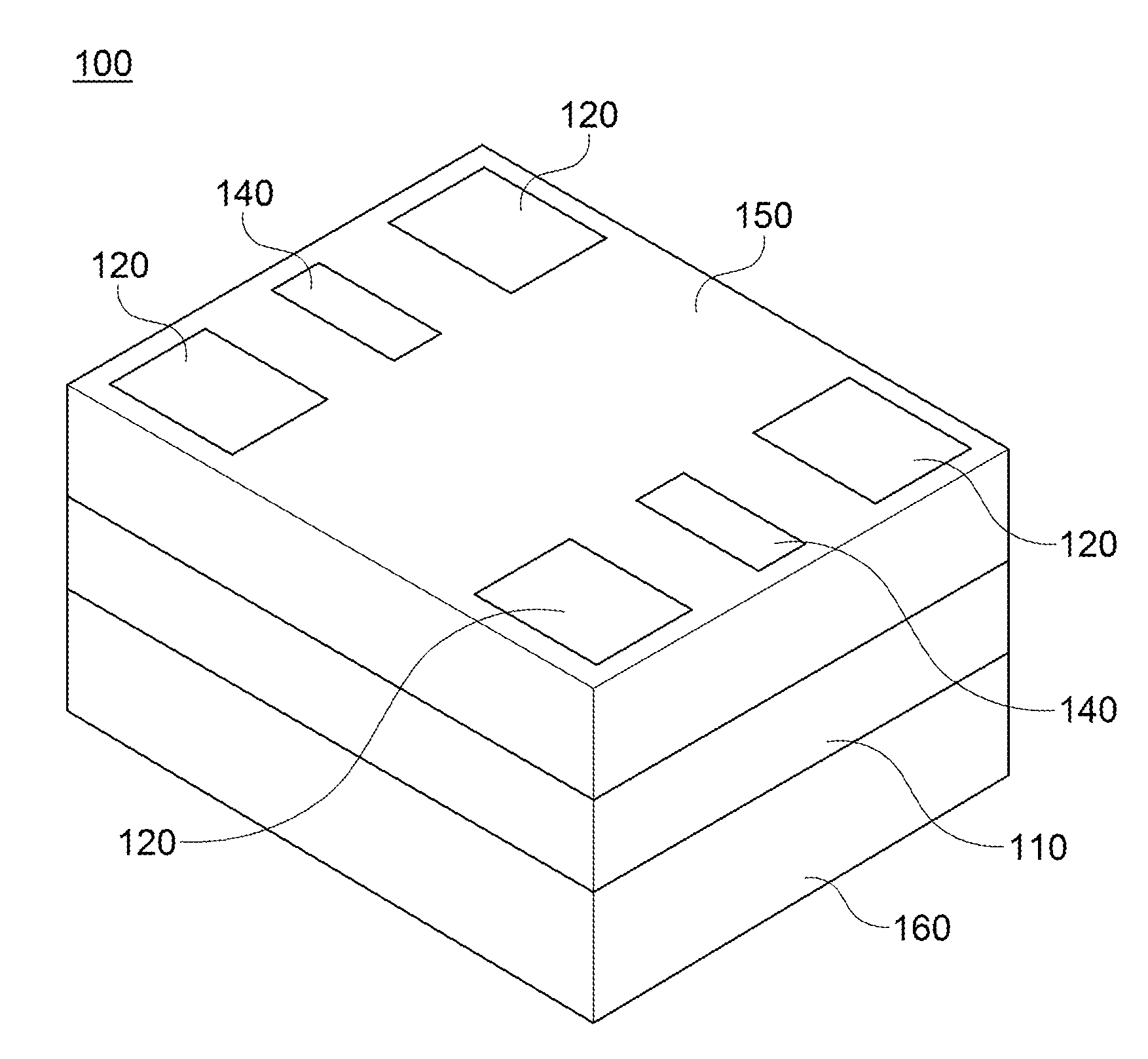
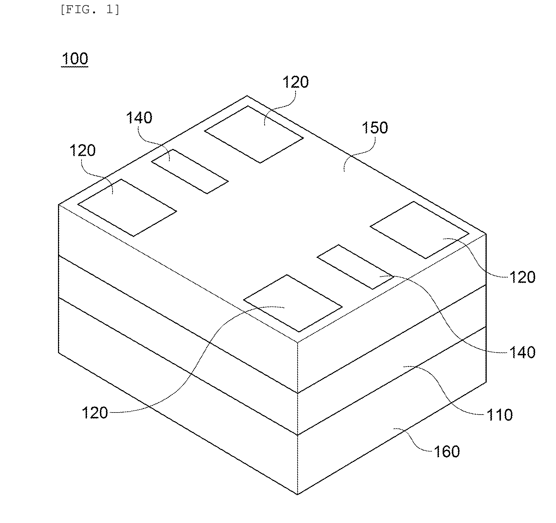
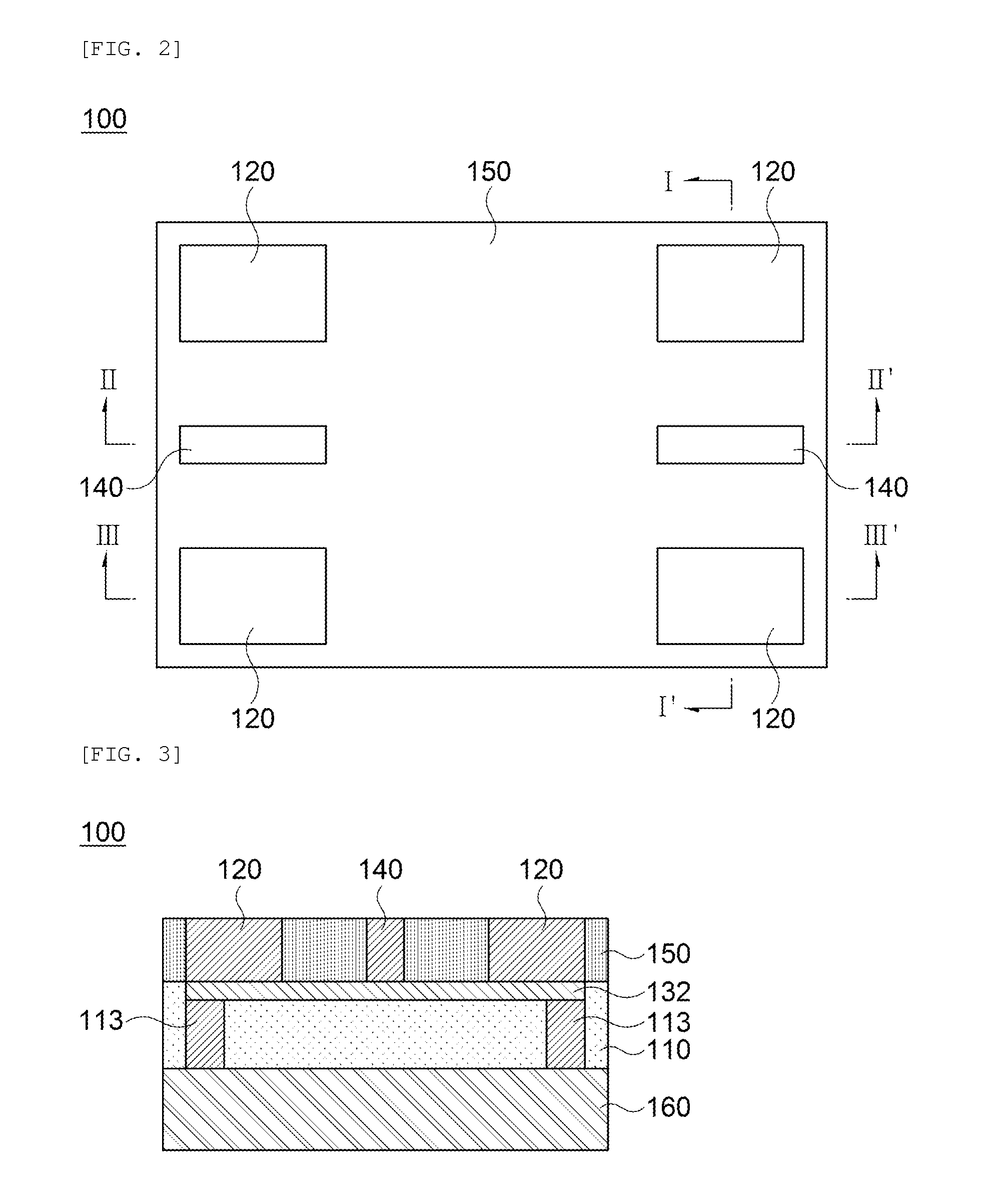
The present invention provides a common mode filter that has a thin chip design. It includes a bar-shaped ESD protection member in the coil layer, specifically between the via electrode and the external terminal. This design can protect the coil layer from overvoltage applied to input / output terminals and ensure a reliable and safe operation of the filter.

Problems solved by technology

However, digitalized, high-speed electronic devices are sensitive to the environments so that signal distortion due to high-frequency noise often occurs.
In the common mode filter disclosed in the Patent Document, however, it is difficult to implement a thinned chip since the separate ESD protection layer for ESD protection is provided in the common mode filter.

Method used


Image

  • Common mode filter
  • Common mode filter
  • Common mode filter

Examples


Embodiment Construction

[0031]Various advantages and features of the present invention and methods for achieving the same will become apparent from the following description of exemplary embodiments with reference to the accompanying drawings. However, the present invention may be modified in many different ways and it should not be limited to exemplary embodiments set forth herein. These exemplary embodiments may be provided so that this disclosure will be thorough and complete, and will fully convey the scope of the invention to those skilled in the art.

[0032]Terms used in the specification are not for limiting the present invention but for illustrating exemplary embodiments. Unless explicitly described to the contrary, a singular form includes a plural form in the specification. The components, steps, operations and / or elements stated herein do not exclude the existence or addition of one or more other components, steps, operations and / or elements.

[0033]Hereinafter, configurations and effects of exempla...


PUM


Abstract

Disclosed herein is a common mode filter, including: first and second coil layers electromagnetically coupled to each other; a pair of external terminals connected to ends of the first coil layer and a pair of external terminals connected to ends of the second coil layer; a first ESD prevention member connecting between the pair of external terminals carrying electric current with the first coil layer and a second ESD prevention member connecting between the pair of external terminals carrying electric current with the second coil layer; and a ground electrode connecting the first ESD prevention member to the second ESD prevention member, wherein the ground electrode has a stepped portion formed at the center.

Description

CROSS REFERENCE(S) TO RELATED APPLICATIONS[0001]This application claims the benefit under 35 U.S.C. Section 119 of Korean Patent Application Serial No. 10-2013-0088881, entitled “Common Mode Filter” filed on Jul. 26, 2013, which is hereby incorporated by reference in its entirety into this application.BACKGROUND OF THE INVENTION[0002]1. Technical Field[0003]The present invention relates to a common mode filter, and more particularly, to a common mode filter having an ESD protection capability.[0004]2. Description of the Related Art[0005]As technologies evolve, electronic devices such as a mobile phone, a home appliance, a personal computer (PC), a personal digital assistant (PDA), a liquid crystal display (LCD), and the like, are being changed from an analog manner into a digital manner, and data processing speed is being increased as the amount of processing data increases. Accordingly, high-speed signal transmission interfaces such as a USB 2.0 interface, a USB 3.0 interface, and ...

Claims


Application Information

Patent Timeline
Patent Type & Authority Applications(United States)
IPC IPC(8): H02H9/04
CPCH02H9/045H02H9/046H01F17/00H01F27/28H01G4/06H02H7/20H03H7/38
Inventor YANG, JU HWANSIM, WON CHULKIM, KWANG MOYANG, JIN HYUCKBANG, HYE WONWI, SUNG KWON
Owner SAMSUNG ELECTRO MECHANICS CO LTD
Learn More