
Electric Connector

a technology of electrical connectors and connectors, applied in the direction of coupling contact members, coupling device connections, coupling parts engagement/disengagement, etc., can solve the problems of unstable electrical connection between the terminals, failure to maintain stable electrical connection, etc., and achieve the effect of high reliability of connection

Active Publication Date: 2015-01-22
IRISO ELECTRONICS CO LTD
View PDF17 Cites 11 Cited by
  • Summary
  • Abstract
  • Description
  • Claims
  • Application Information

AI Technical Summary

Benefits of technology

The technical effect of this patent is that it describes a way to maintain a reliable electrical connection between a plug terminal and a socket terminal even when exposed to impact or vibrations. This is achieved by locking the connection between the two terminals using a locking portion on the socket terminal and a contact surface on the plug terminal. This prevents the plug from being pulled out from the socket with a force that is weaker than or equal to a predetermined pulling force. Additionally, impurities adhering to the plug terminal can be removed to further stabilize the electrical connection.

Problems solved by technology

Although an electric connector used in such an environment can maintain the plug and the socket in a correct fitting state at the beginning, it may fail to maintain stable electrical connection due to an insufficient contact between the terminals upon receipt of an impact or vibrations during use.
Examples of causes that make an electrical connection between the terminals unstable include impurities such as substrate residues or dust adhering to the plug terminal.

Method used


Image

  • Electric Connector
  • Electric Connector
  • Electric Connector

Examples


sixth embodiment

Modified Example of Sixth Embodiment

[0105]The sixth embodiment has described an example in which the inner walls 4c1 to 4c4 of each recess 4c are replaced by the inclined surfaces 14a to 14d. In contrast, the inclined surfaces 14a to 14d may be provided as, for example, the inner walls of each through hole 11. The inclined surfaces 14a to 14d in such a structure can have the operations and effects of the through holes 11 according to the third embodiment as well as the guide function according to the sixth embodiment.

Seventh Embodiment (FIGS. 11A and 11B)

[0106]The sixth embodiment has described an example in which each recess 4c has a back wall 4c5. As illustrated in FIGS. 11A and 11B, however, a recess 4c defined by inclined surfaces 14a to 14d and having an apex 14e, which is the deepest point of the contact portion 4d, may be formed instead. In this structure, the inclined surfaces 14a and 14c can guide the front connection portion 5a to the apex 14e in the Z direction while the ...


PUM


Abstract

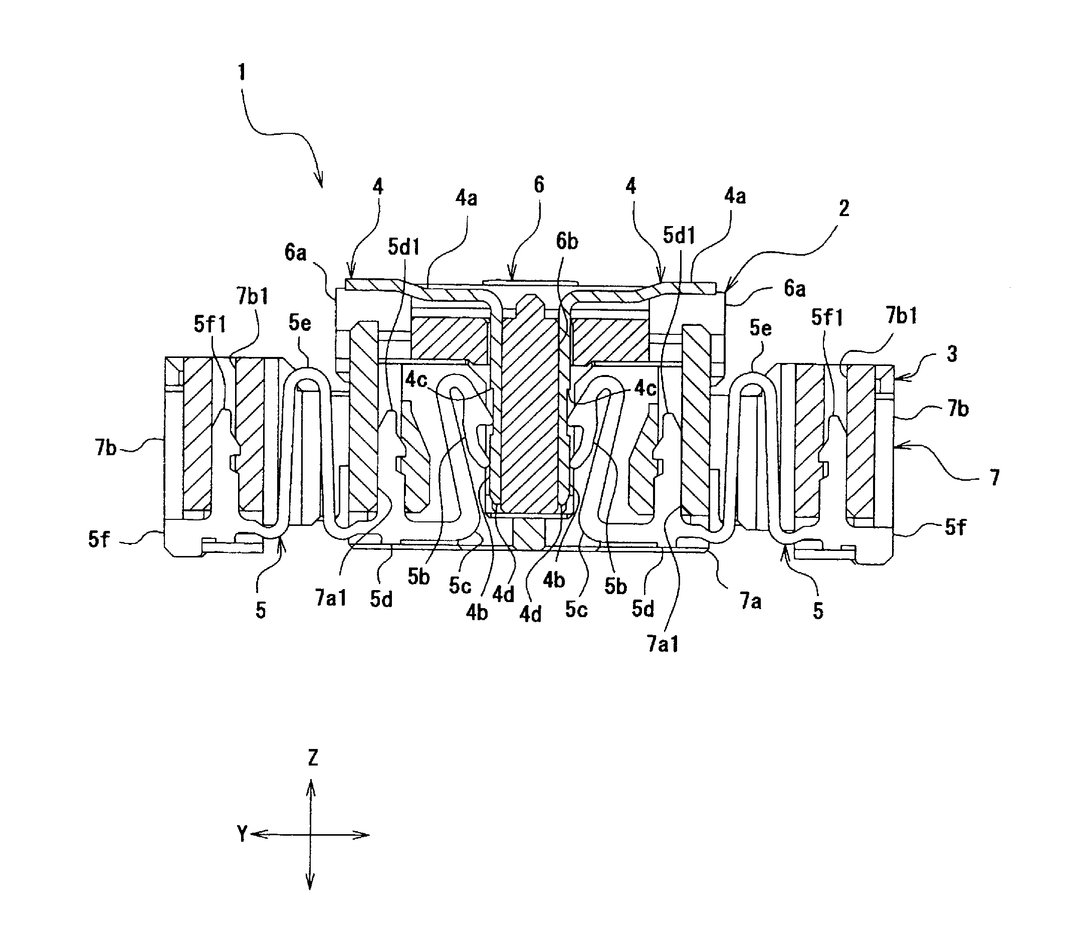
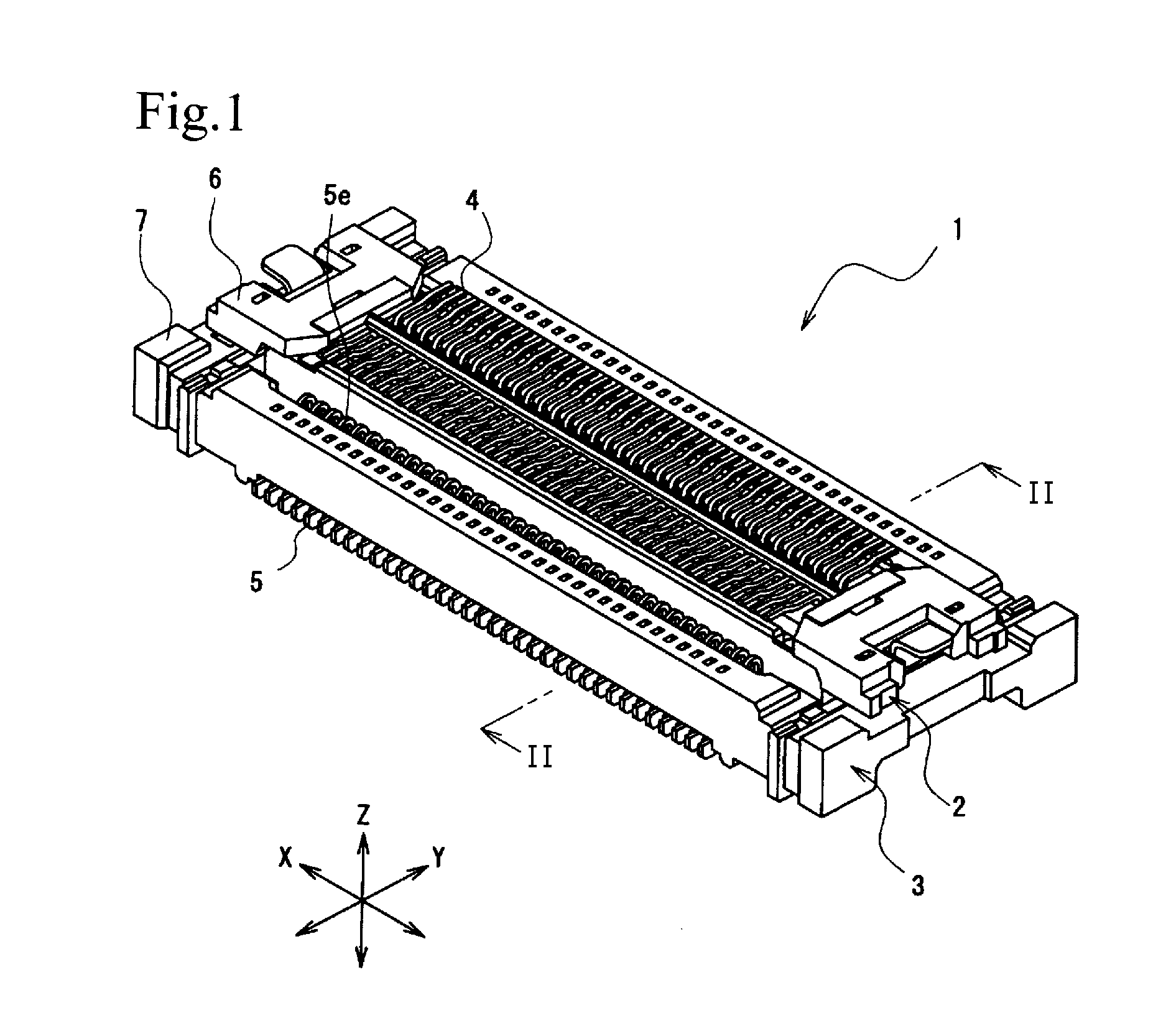
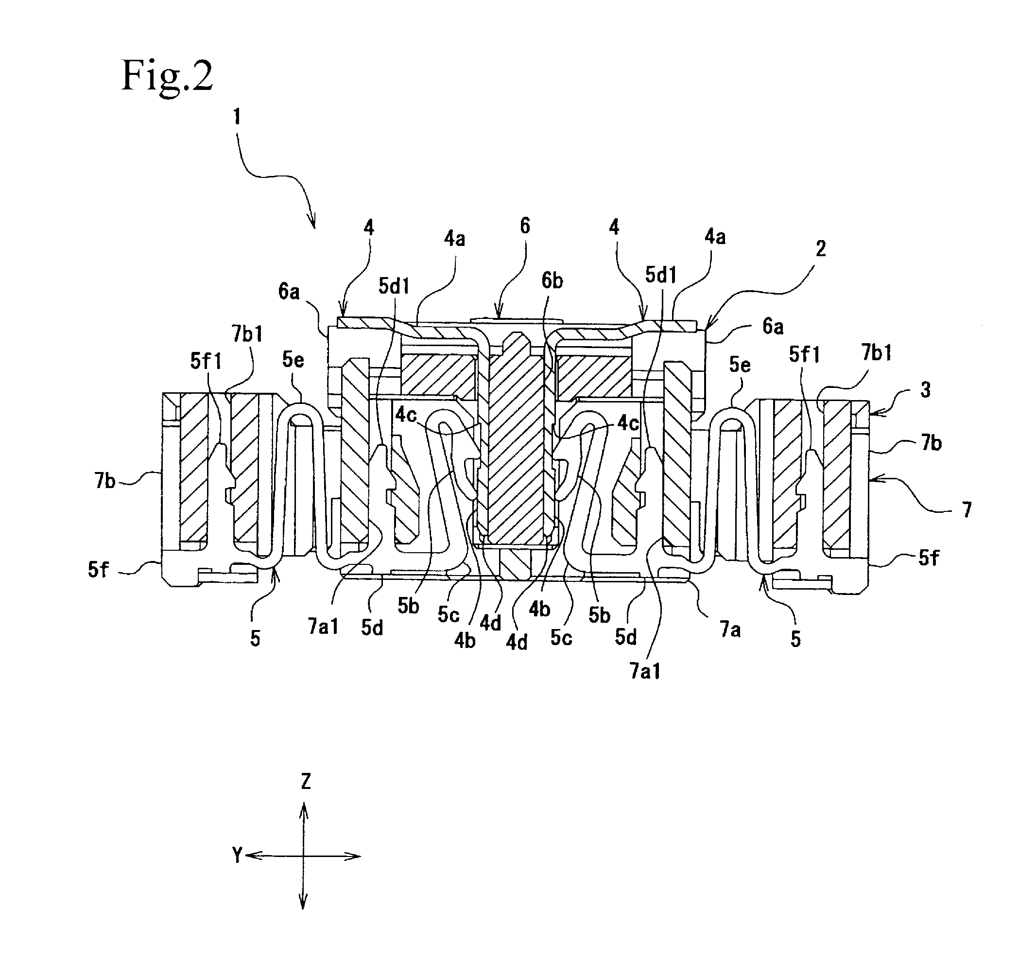
A socket terminal includes a front connection portion that comes into contact with a plug terminal, in which a recess having an inner wall is formed in a contact surface that comes into contact with the front connection portion. The front connection portion is locked on the inner wall by coming into contact with the inner wall when moving in a direction in which the plug terminal is pulled out from the socket terminal. The front connection portion also includes a contact edge that wipes impurities off the contact surface. An electrical connection between the socket terminal and the plug terminal can be maintained by locking the socket terminal on the inner wall even with an application of vibrations in directions in which the plug terminal is inserted and pulled out. Since the contact edge can remove the impurities, the electrical connection between the terminals can be stabilized.

Description

BACKGROUND OF THE INVENTION[0001]1. Field of the Invention[0002]The present invention relates to an electric connector that electrically connects circuit boards to each other.[0003]2. Description of the Related Art[0004]A floating connector that includes a plug and a socket and that can correct displacement between the plug and the socket relative to each other is known to date as an electric connector that maintains a connection between circuit boards regardless of an application of vibrations. Examples of electric connectors that have been developed to, particularly, highly reliably connect terminals to each other include an electric connector in which an S-shaped movable portion is provided on a socket terminal so that the socket is movable relative to the plug (Japanese Unexamined Patent Application Publication No. 2011-249076). Such an electric connector can maintain the plug and the socket in a correct fitting state due to the movable portion of the socket terminal absorbing v...

Claims


Application Information

Patent Timeline
Patent Type & Authority Applications(United States)
IPC IPC(8): H01R13/62
CPCH01R13/62H01R13/112H01R13/20H01R12/716H01R13/6315H01R13/213H01R13/26H01R12/91
Inventor KOBAYASHI, HIROAKISHINDO, HIDEHIROMITSUZUKA, SHIGERU
Owner IRISO ELECTRONICS CO LTD
Learn More