
Pressure transmitter having an isolation assembly with a two-piece isolator plug

a technology of isolator and isolation assembly, which is applied in the direction of fluid pressure measurement by mechanical elements, instruments, measurement devices, etc., can solve the problems of adding significantly to the material cost of the process transmitter, and achieve the effect of maintaining corrosion resistance to corroded process environments and reducing the material cost of the isolator plug and the transmitter

Active Publication Date: 2015-01-22
ROSEMOUNT INC
View PDF71 Cites 17 Cited by
  • Summary
  • Abstract
  • Description
  • Claims
  • Application Information

AI Technical Summary

Benefits of technology

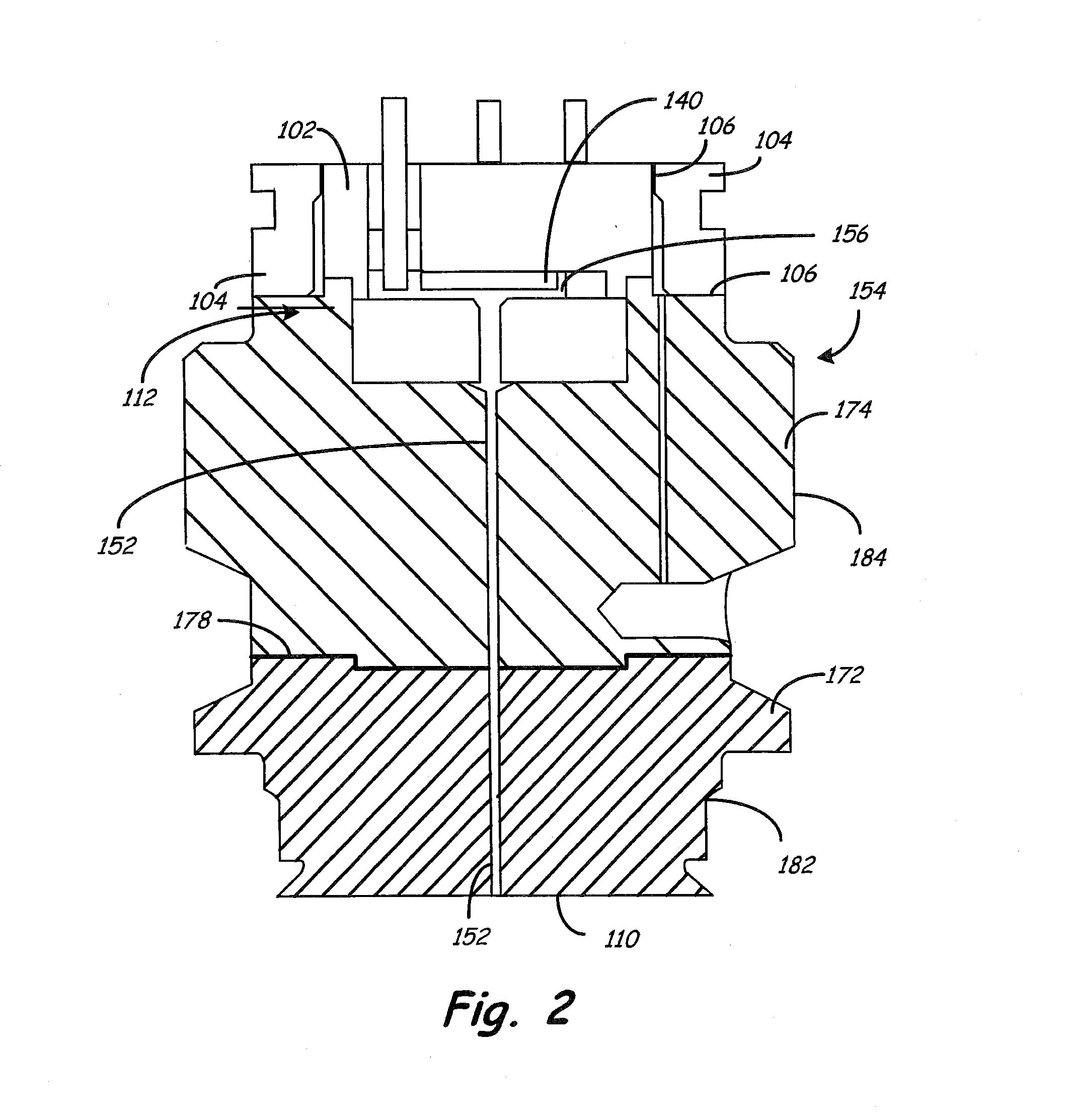
The patent text describes a design for an isolator plug used in process lines. The design includes a lower plug portion that is wetted by process fluid when the pressure transmitter is connected to the process line, while the upper plug portion is not wetted. The lower plug portion is made from a more corrosion-resistant material, reducing material costs while maintaining corrosion resistance. The upper plug portion can be made from a stainless steel material, and the lower plug portion can be made from Alloy C-27. The design also allows for the use of different materials for either the upper or lower plug portion, depending on the specific needs of the process.

Problems solved by technology

Such corrosion resistant materials, such as Alloy C-276, add significantly to the material cost of the process transmitter.

Method used


Image

  • Pressure transmitter having an isolation assembly with a two-piece isolator plug
  • Pressure transmitter having an isolation assembly with a two-piece isolator plug
  • Pressure transmitter having an isolation assembly with a two-piece isolator plug

Examples


Embodiment Construction

[0013]The present disclosure provides an isolation assembly for a pressure sensor in a pressure transmitter which isolates one or more pressure sensors of the transmitter from corrosive process fluids, while allowing the material costs associated with manufacturing the transmitter to be reduced.

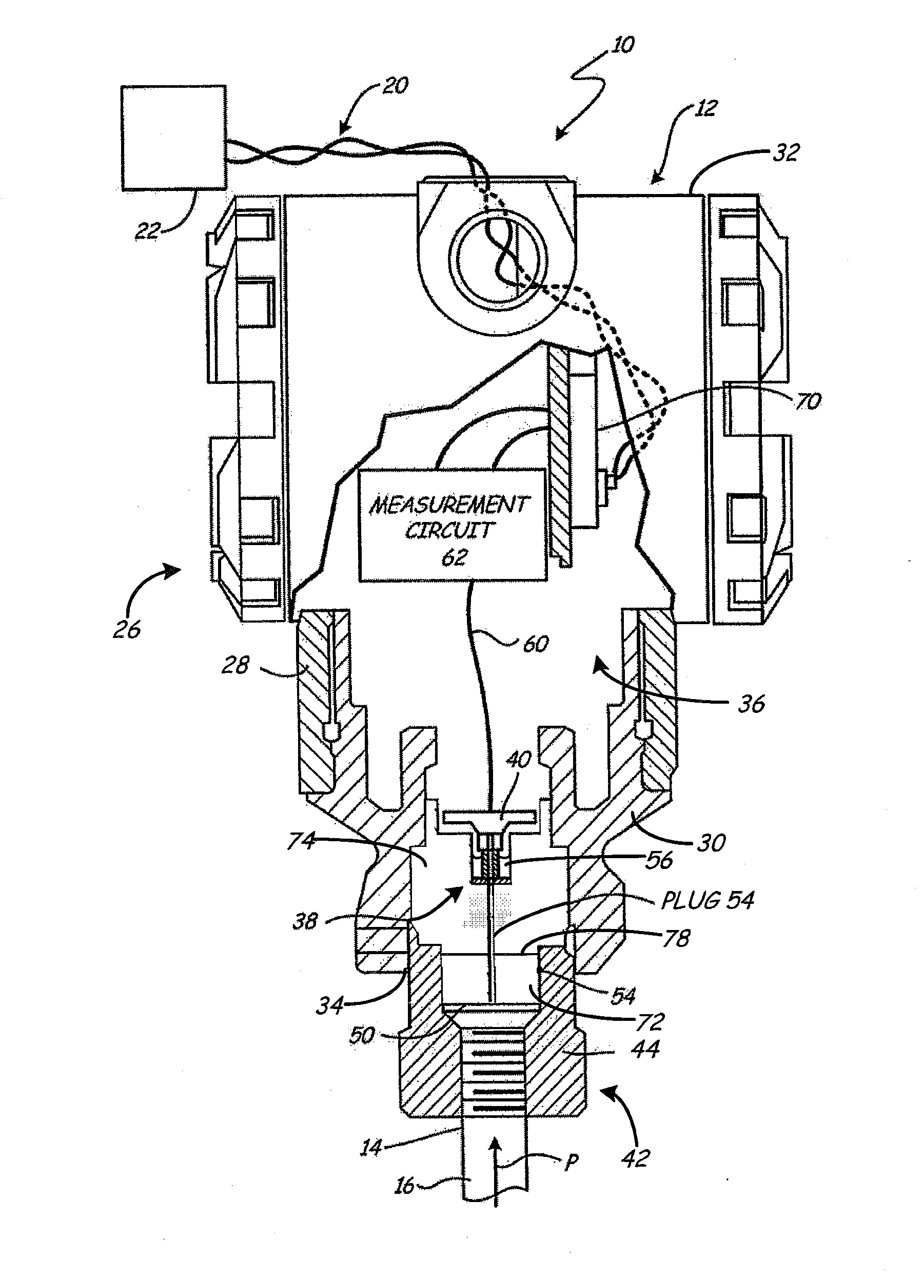
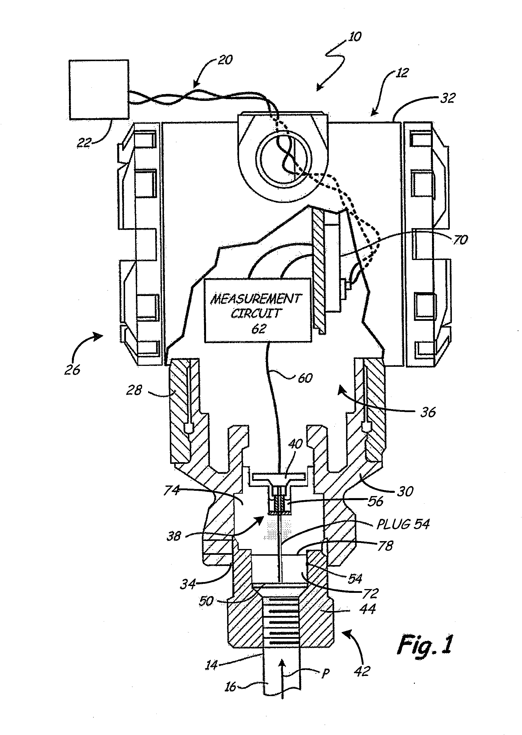
[0014]FIG. 1 is a diagram showing a process control or measurement system 10 which includes a pressure transmitter 12 coupled to process piping 14 which carries a process fluid 16. (Transmitter 12 is a measurement component of system 10.) The process fluid 16 applies a pressure P to the pressure transmitter 12. Pressure transmitter 12 provides an output, for example on a two-wire process control loop 20 to a remote location such as a control room 22. The process control loop 20 can operate in accordance with any appropriate protocol. In one configuration, process control loop 20 comprises a two-wire process control loop in which an analog current level is used to represent a “process variable...


PUM

PropertyMeasurementUnit
pressureaaaaaaaaaa
corrosion resistanceaaaaaaaaaa
temperaturesaaaaaaaaaa

Abstract

A pressure transmitter connectable to a process line provides an output responsive to a pressure in the process line. The transmitter includes a housing having a base with a process end coupled to an interior cavity formed in the housing, a sensor for sensing the pressure and an isolating assembly mounted at the process end of the housing and isolating fluid in the process line from the interior cavity. The isolating assembly includes an isolation diaphragm configured to be fluidically coupled to the process pressure in the process line, and an isolator plug positioned in the process of the housing adapter. The isolator plug having a lower plug portion providing a first end surface adjacent the isolation diaphragm, an upper plug portion providing a second end surface distally spaced from the first end surface and adjacent a sensor cavity in which the sensor is positioned, a connection mechanism connecting the lower and upper plug portions, and a capillary filled with isolation fluid and extending from the first end surface through the lower and upper plug portions to the second end surface thereby coupling the pressure through the isolation diaphragm and the capillary to the sensor cavity and the sensor. The upper plug portion is formed from a first material and the lower plug portion is formed from a second material having higher corrosion resistance than the first material.

Description

CROSS-REFERENCE TO RELATED APPLICATION[0001]This Application is a Section 371 National Stage Application of International Application No. PCT / CN2013 / 079695, filed Jul. 19, 2013, not yet published, the contents of which are hereby incorporated by reference in their entirety.BACKGROUND OF THE INVENTION[0002]The present invention relates to industrial process pressure transmitters. More particularly, the present invention relates to isolator plugs of isolator mounting assemblies for supporting a pressure sensor and for isolating the pressure sensor and an interior cavity of the transmitter from a process line fluid to be measured.[0003]Industrial process control systems are used to monitor and control industrial processes which produce or transfer liquids or the like. In such systems, it is typically important to measure “process variables” such as temperatures, pressures, flow rates, and others. Process control transmitters are used to measure such process variables and transmit infor...

Claims


Application Information

Patent Timeline
Patent Type & Authority Applications(United States)
IPC IPC(8): G01L19/06
CPCG01L19/06G01L19/0645Y10T29/49815G01L7/082G01L19/0046G01L19/003
Inventor ERIKSEN, CHRISTOPHER LEEXU, LIHONG
Owner ROSEMOUNT INC
Learn More