
Composite sliding bearing and wind power generating device using the same bearing

a technology of composite sliding bearing and wind power generation device, which is applied in the direction of wind energy generation, waterborne vessels, machines/engines, etc., can solve the problems of taking a lot of trouble over maintenance, and achieve the effects of improving bearing function, superior sliding characteristics, and low friction coefficien

Active Publication Date: 2015-01-15
FUJI ELECTRIC CO LTD
View PDF2 Cites 52 Cited by
  • Summary
  • Abstract
  • Description
  • Claims
  • Application Information

AI Technical Summary

Benefits of technology

The invention is about a new design for a composite sliding bearing that can be used in wind power generating devices. This new design allows for a smaller and more compact bearing, similar to a double row tapered roller bearing. The bearing pads have a tilting function, and they are made from a low friction material that also has superior sliding characteristics. The bearing pads also have elastic support seats for better stability and lubrication. This new design also simplifies maintenance work, as it allows for easier inspection, replacement, and reassembly of the bearing pads. Overall, this new design improves the performance and workability of wind power generating devices.

Problems solved by technology

However, there is the problem in a gear type speed increasing system that the noise is large, and there also arise a lot of problems, thus taking a lot of trouble over maintenance.

Method used


Image

  • Composite sliding bearing and wind power generating device using the same bearing
  • Composite sliding bearing and wind power generating device using the same bearing
  • Composite sliding bearing and wind power generating device using the same bearing

Examples


Embodiment Construction

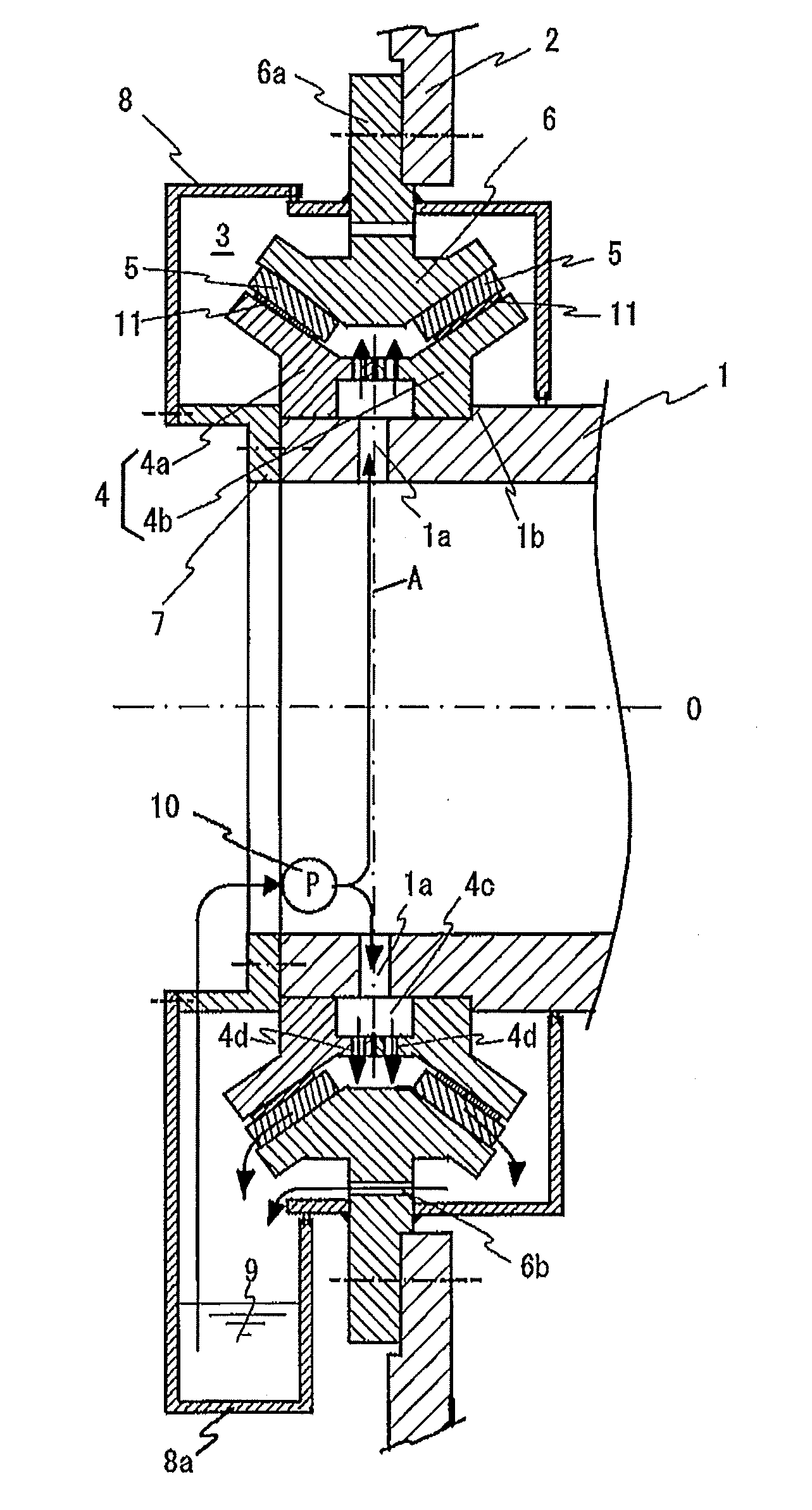
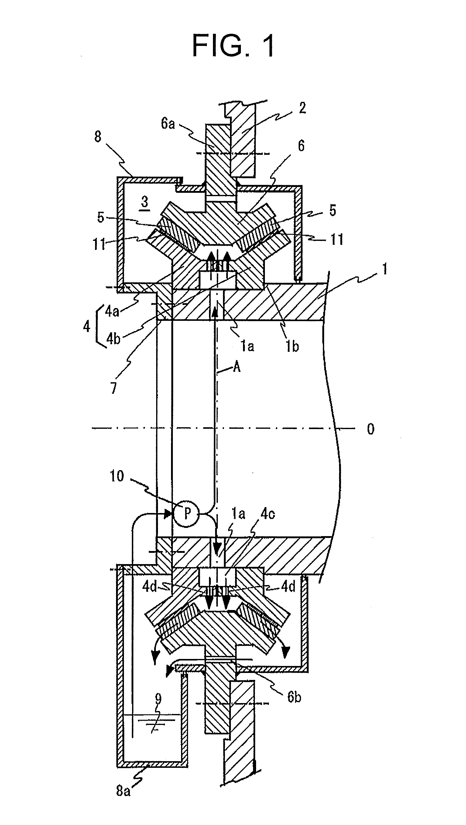
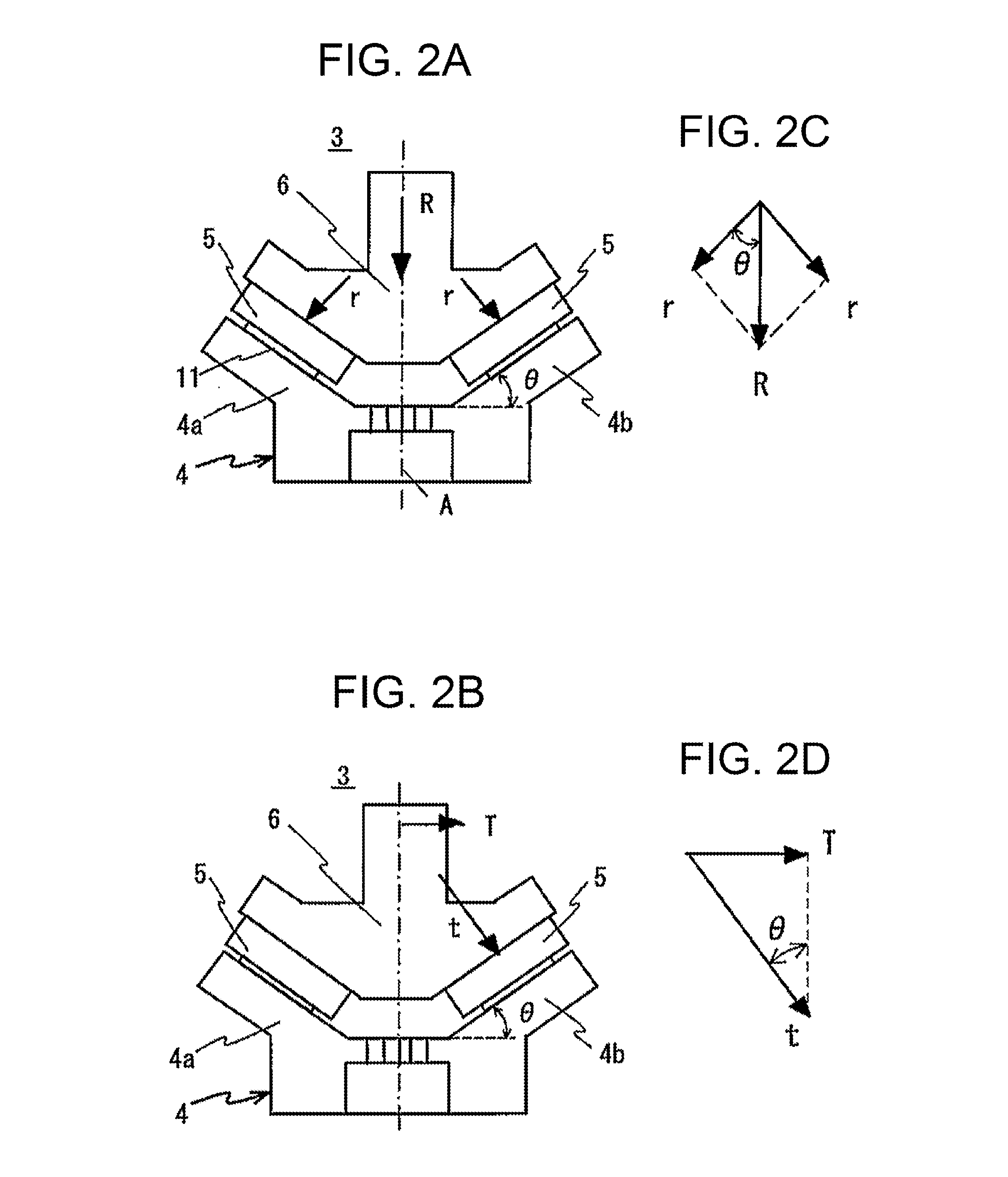
[0042]Hereafter, a description will be given, based on working examples shown in FIGS. 1 to 3, of an embodiment of a composite sliding bearing according to the invention and a wind power generating device equipped with the composite bearing.

[0043]Firstly, FIG. 1 shows an assembled structure of the composite sliding bearing according to the invention. In FIG. 1, 1 is a cylindrical hollow fixed shaft (horizontal shaft), 2 is a rotor center of a generator, and 3 is a composite sliding bearing supporting the rotor center 2 on the fixed shaft 1. 0 in FIG. 1 is the axial center of the fixed shaft 1.

[0044]Herein, the composite sliding bearing 3 is formed of an assembled body of an inner ring 4, formed of split rings 4a and 4b which are halved by an axially central dividing surface A and disposed fitted on the fixed shaft 1, on the outer diameter surface of which V-section inclined surfaces are formed, bearing pads 5 disposed separated on the inclined surfaces of the respective split rings ...


PUM

PropertyMeasurementUnit
diameter sizeaaaaaaaaaa
outer diameteraaaaaaaaaa
inner diameteraaaaaaaaaa

Abstract

A composite sliding bearing is disclosed. The composite sliding bearing has an inner ring, formed of split rings halved by a center in an axial direction, which has V-section inclined surfaces formed on the outer diameter surfaces of the split rings, bearing pads disposed separately on the inclined surfaces of the split rings along the outer diameter surface of the inner ring, and an outer ring on the inner diameter surface of which is formed a V-section umbrella-shaped inclined surface corresponding to the outer diameter surface of the inner ring. A radial load and axial load applied to the bearing are supported by sliding the inner diameter surface of the outer ring on the sliding surfaces of the bearing pads in a condition in which the bearing pads are fluid lubricated.

Description

[0001]This application is a continuation of international application number PCT / JP2013 / 066677, filed Jun. 18, 2013, and claims the benefit of priority of Japanese patent application JP PA 2012-138017, filed Jun. 19, 2012. The disclosures of the international application and the Japanese priority applications are incorporated herein by reference.TECHNICAL FIELD[0002]The present invention relates to a composite sliding bearing which is applied to a main shaft's bearing of a wind power generating device or the like, thus supporting a radial load and axial load, and to a configuration of a wind power generating device employing the sliding bearing.BACKGROUND ART[0003]As is well known, the drive type of a wind power generation device is classified roughly into an overdrive type (for example, refer to PTL 1 and PTL 2) and a direct drive type (for example, refer to PTL 3).[0004]That is, the number of rotation of the horizontal axis wind turbine employed in many current wind power generati...

Claims


Application Information

Patent Timeline
Patent Type & Authority Applications(United States)
IPC IPC(8): F03D11/00F16C41/00F16C33/10F16C33/20F16C17/10F16C27/02F03D80/00F03D80/70
CPCF16C27/02F16C17/10F16C33/205F16C33/1065F03D11/0008F16C41/004F05B2240/50F05B2260/98F16C2300/14F16C2360/31F03D80/70F16C27/063F16C33/06F16C33/103F16C33/20F16C2208/36F16C2208/32F16C33/1055Y02E10/72
Inventor SATO, SHOJIHOSHI, MASAHIRO
Owner FUJI ELECTRIC CO LTD
Learn More