
IR emissive display facilitating remote eye tracking

Inactive Publication Date: 2015-01-15
SAMSUNG DISPLAY CO LTD
View PDF6 Cites 26 Cited by
  • Summary
  • Abstract
  • Description
  • Claims
  • Application Information

AI Technical Summary

Benefits of technology

This patent is about a new display system that uses infrared (IR) light to track the position of a user's eyes. The system includes a panel with IR pixels that emit light, an IR sensor that collects the reflected light, and a controller that controls the IR pixels and sensor. The system can detect the user's gaze direction by emitting IR light and sensing the reflected light. This technology is more robust and cost-effective than existing remote eye tracking solutions, and can work effectively even when wearing eyeglasses. The technical effect of the patent is to provide a better and more practical solution for remote eye tracking.

Problems solved by technology

Current approaches to determine where an observer is looking on a display screen have failed to be widely available in consumer devices.
Such solutions are large standalone systems and have performance problems, such as when a user is wearing normal eyeglasses (which can cause strong specular reflection off the lenses that confound eye tracking of existing devices).

Method used


Image

  • IR emissive display facilitating remote eye tracking
  • IR emissive display facilitating remote eye tracking
  • IR emissive display facilitating remote eye tracking

Examples


Embodiment Construction

[0032]Example embodiments of the present invention will now be described with reference to the accompanying drawings. In the drawings, the same or similar reference numerals refer to the same or similar elements throughout. Herein, the use of the term “may,” when describing embodiments of the present invention, refers to “one or more embodiments of the present invention.” In addition, the use of alternative language, such as “or,” when describing embodiments of the present invention, refers to “one or more embodiments of the present invention” for each corresponding item listed.

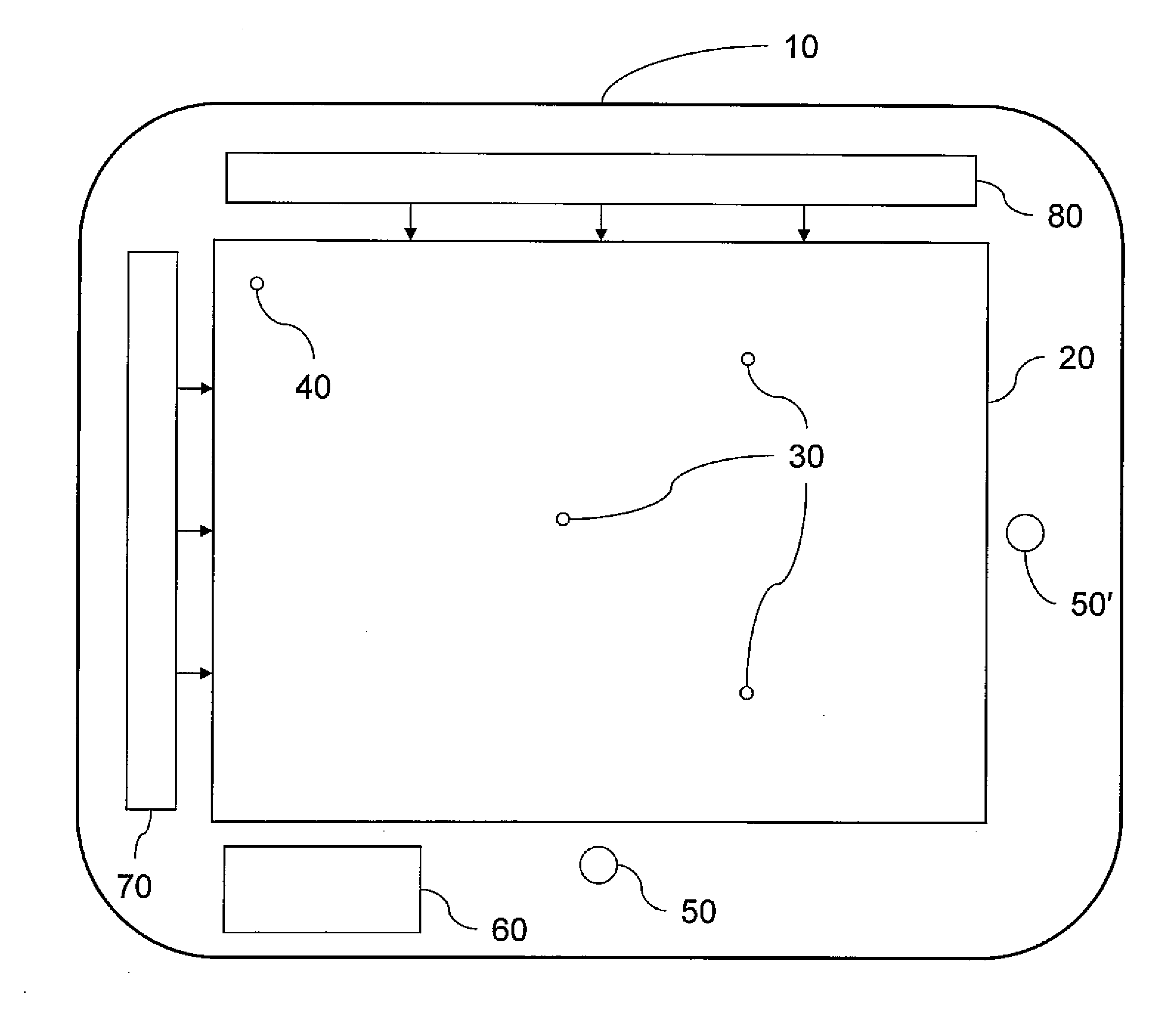
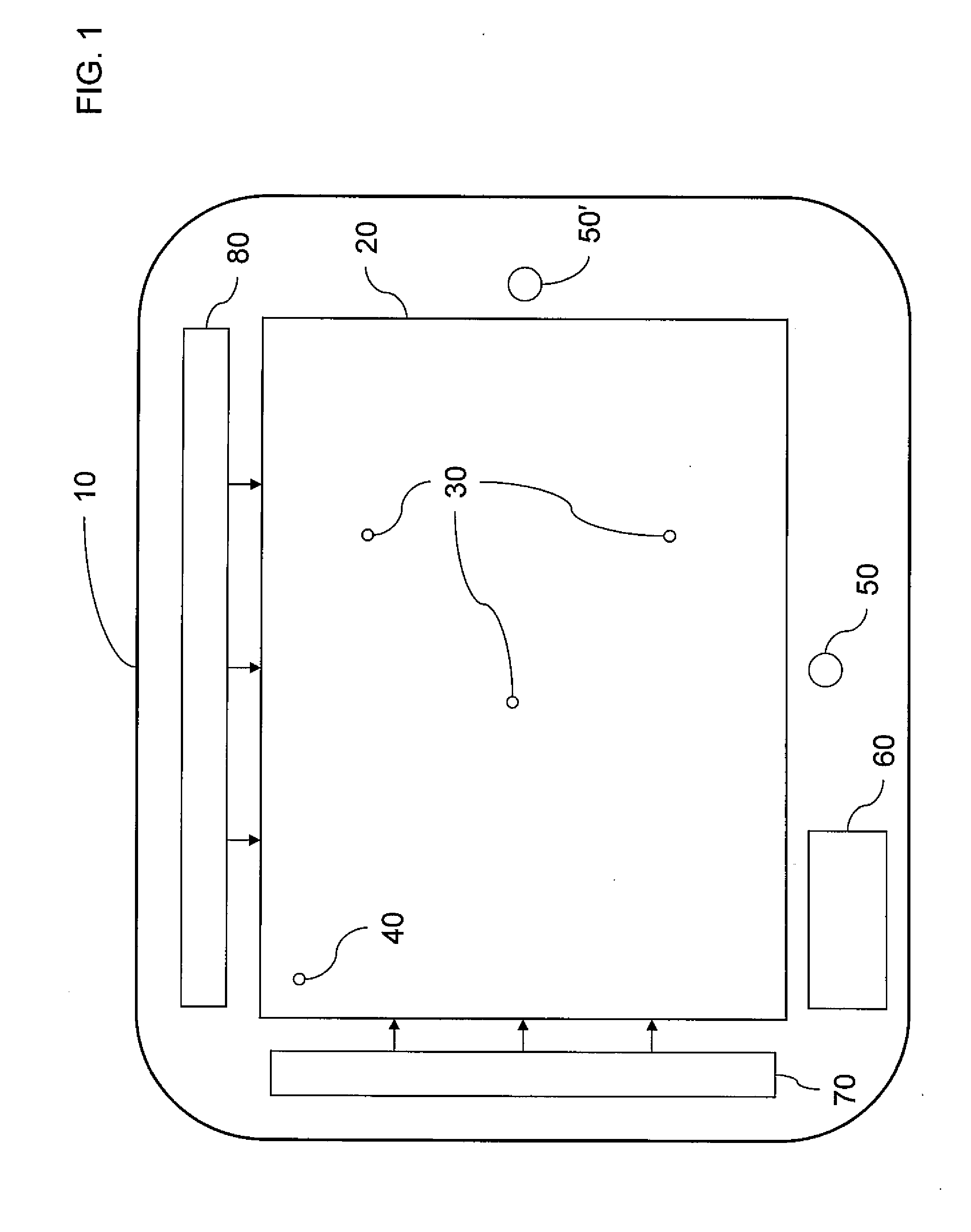
[0033]In one or more embodiments, a display device is provided. The display device includes IR emissive pixels and one or more image sensors. The IR emissive pixels are arranged in a two-dimensional (2D) pattern or arrangement, such as an array of emitters or a dispersed arrangement along both dimensions. For example, the display device may use a display panel having embedded light emitters (e.g., IR emitters...


PUM


Abstract

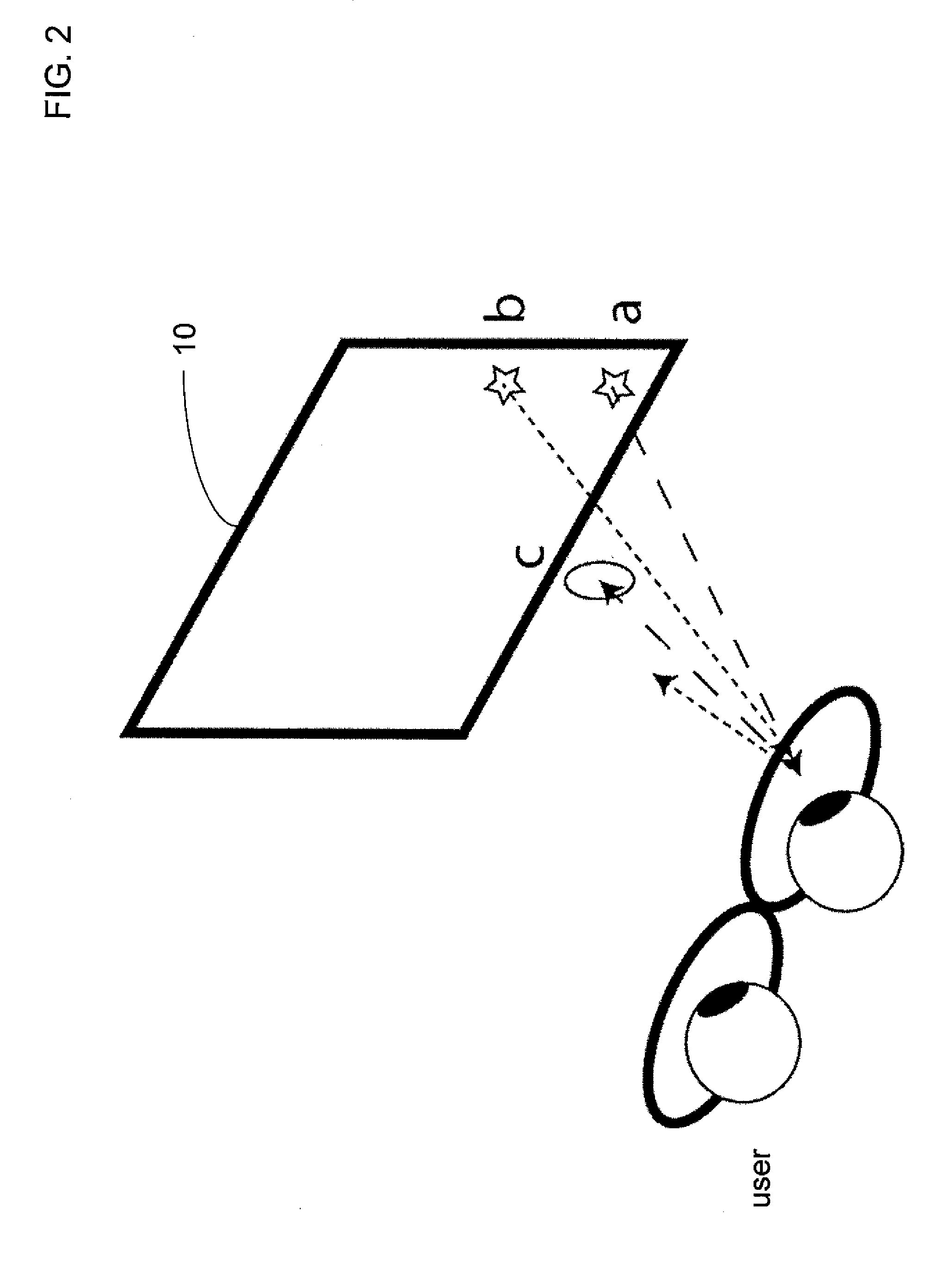
An infrared (IR) emissive display device includes a display panel, an IR sensor, and a controller. The display panel includes IR pixels configured to emit IR light and arranged in a first two-dimensional (2D) pattern. The IR sensor is configured to sense IR signals emitted from the IR pixels and reflected off a user of the display device. The controller is configured to control the IR pixels, the IR signals, and the IR sensor to detect a gaze direction of an eye of the user. A method of facilitating remote eye tracking of the user on the display device includes emitting the IR signals from the IR pixels toward the user, sensing the IR signals reflected off the user with the IR sensor, and detecting the gaze direction of the user's eye from the sensed IR signals.

Description

CROSS-REFERENCE TO RELATED APPLICATION(S)[0001]This application claims priority to and the benefit of U.S. Provisional Application 61 / 845,118, entitled “IR EMISSIVE DISPLAY FACILITATING REMOTE EYE TRACKING,” filed on Jul. 11, 2013, the entire content of which is herein incorporated by reference.BACKGROUND[0002]1. Field[0003]Aspects of embodiments of the present invention relate to an infrared (IR) emissive display capable of facilitating remote eye tracking.[0004]2. Related Art[0005]Gaze tracking (or eye tracking) permits electronic devices, such as computers, to know where a user is looking (such as on a display screen) without requiring further input from the user. Current approaches to determine where an observer is looking on a display screen have failed to be widely available in consumer devices. Some solutions use specially designed eyewear to directly track the eye. Other solutions do not use eyewear, but instead use a detached or remote device to track the eye. The existing ...

Claims


Application Information

Patent Timeline
IPC IPC(8): G06F3/01H04N5/33
CPCG06F3/013H04N5/33
Inventor HOFFMAN, DAVID M.
Owner SAMSUNG DISPLAY CO LTD
Learn More