
Method of production and apparatus for production of reduced iron

a technology of equipment and iron, applied in the direction of metal processing, climate sustainability, checking devices, etc., can solve the problems of environmental problems, extreme difficulty in handling, and another problem to take no

Inactive Publication Date: 2015-01-15
TETSUGEN CO LTD
View PDF2 Cites 6 Cited by
  • Summary
  • Abstract
  • Description
  • Claims
  • Application Information

AI Technical Summary

Benefits of technology

The present invention solves problems by directly treating fine powder iron oxide, reducing treatment at lower temperatures, and using an external heat type rotary kiln for uniform heating. The CO gas generated during reduction treatment can be utilized as a heat source for the rotary kiln, resulting in energy recovery. The use of both an internal and external rotary kiln improves stability and prevents damage to the equipment. The reduction treatment also suppresses the formation of a dam ring and allows for efficient recovery and recycling of the generated CO gas. The use of corn starch as a binder improves crushing strength and reduces powder formation during processing. These technical effects make the process more efficient, compact, and environmentally friendly.

Problems solved by technology

Converter sludge is muddy in state, so is extremely difficult to handle.
Further, there are also environmental problems due to the dust etc.
When recycling the converter sludge as an iron source, there is another problem to take note of.

Method used


Image

  • Method of production and apparatus for production of reduced iron
  • Method of production and apparatus for production of reduced iron
  • Method of production and apparatus for production of reduced iron

Examples


example 1

[0114]Below, the present invention will be explained by examples obtained by a test plant. Table 1 shows the chemical components of non-oxidative cured products which were obtained by drying converter sludge which was used in a later explained test operation in a N2 stream. The M.Fe was a considerably high 19.2%. The distribution of particle size of this converter sludge was measured by a laser diffraction and scattering type particle size distribution measuring apparatus (microtrack) and was found to be D10=0.5 μm, D50=1.4 μm, and D90=3.6 μm. As explained above, D50 means the particle size where the cumulative frequency from the fine particles corresponds to 50% in the cumulative particle size distribution. Similarly, D10 means the particle size where the cumulative frequency from the fine particles corresponds to 10%, D90 means the one which it corresponds to 90%.

TABLE 1T•FeM•FeFeOFe2O3CZnDried product of70.419.264.71.214.761.81converter sludge in N2stream (mass %)

[0115]Table 2 sh...

example 2

[0145]Next, the above test apparatus was used to run tests for production of reduced iron by carbon-containing shaped materials which were produced by converter type pretreatment furnace sludge and electric furnace dust (dust generated at electric type iron melting furnace). Table 4 shows the chemical components of a non-oxidative cured product which was dried in a nitrogen (N2) stream. Table 5 shows the distribution of the particle size of these.

[0146]To the above material, a carbonaceous material constituted by powdered coke was added to give a C equivalent of 1.0 (Zn is all ZnO, while the C equivalent for FeO+Fe2O3+ZnO was 1.0). Using the same method as at the time of Example 1, an extruder was used to produce 15 mmφ×20 mm shaped materials for use for a reduction test. The test conditions were made the same as Test No. 5 of Example 1. The results of the tests are shown in Table 6. These test results confirmed that in each case, the properties of reduced iron by the RHF method (se...


PUM

PropertyMeasurementUnit
Diameteraaaaaaaaaa
Diameteraaaaaaaaaa
Particle sizeaaaaaaaaaa

Abstract

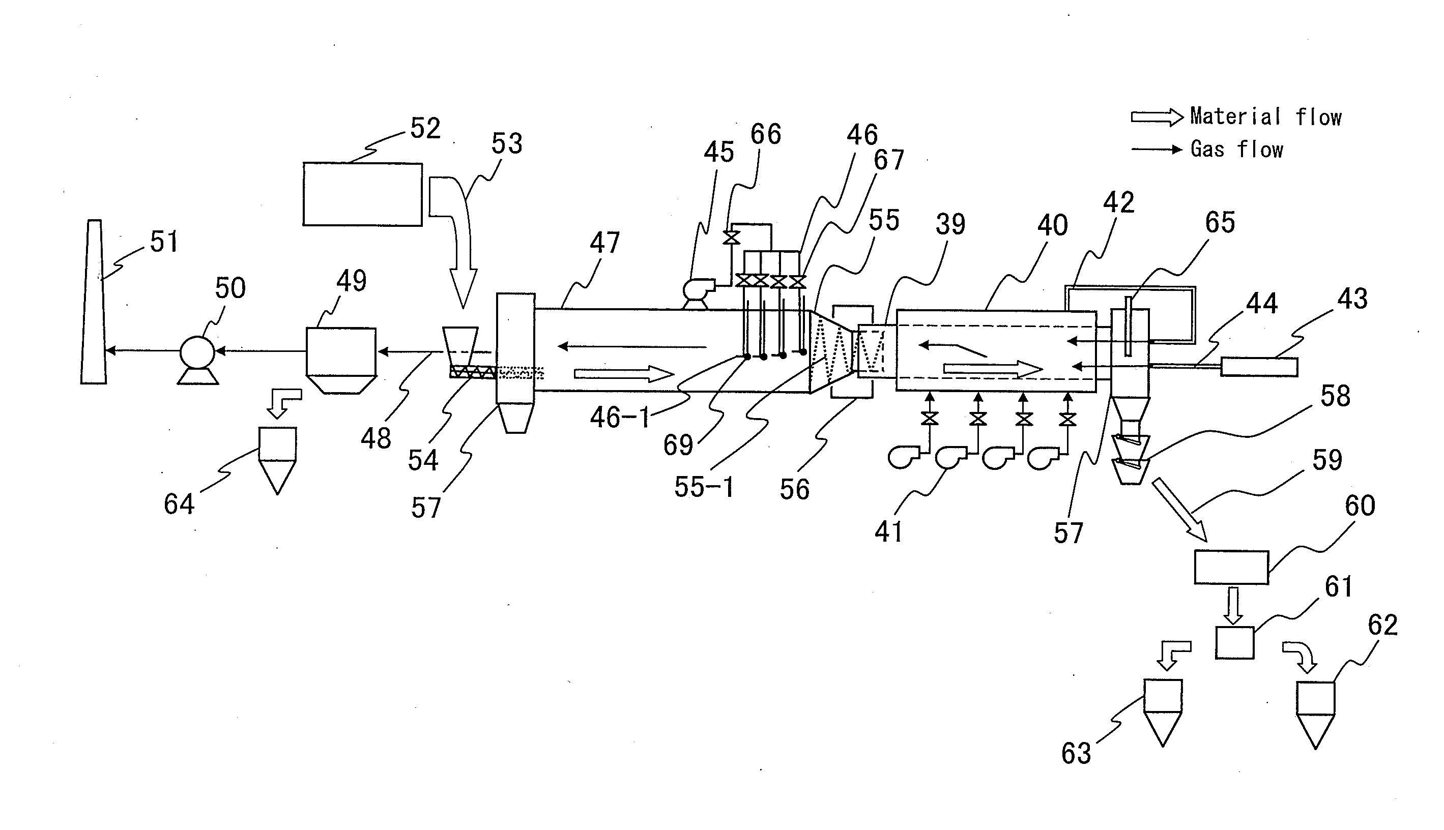
The present invention relates to a method and apparatus for producing reduced iron from ironmaking dust which contains iron oxide which is generated at an ironmaking plant, takes note of the rotary kiln reduction method which does not require pretreatment of the dust, and has as its problem the pursuit of facilities which achieve further improvement of heat efficiency and stable operation.To solve this problem, the present invention is characterized by heating and reducing carbon-containing shaped materials in a single closed space in which an internal heat type rotary kiln and an external heat type rotary kiln are arranged in series and including at least the insides of the two rotary kilns during which making the reduced exhaust gas which is generated at the external heat type rotary kiln burn inside of the internal heat type rotary kiln.

Description

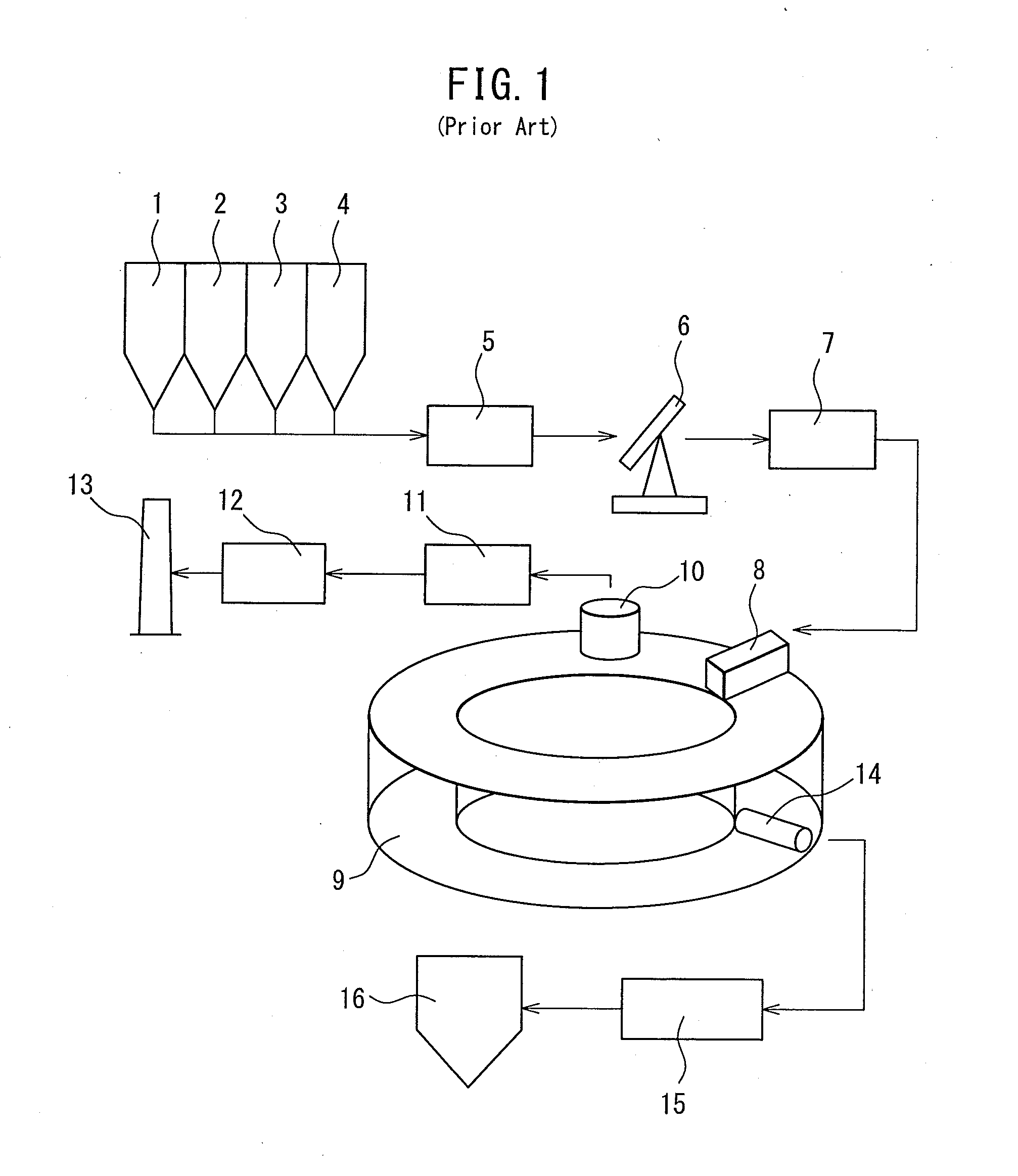
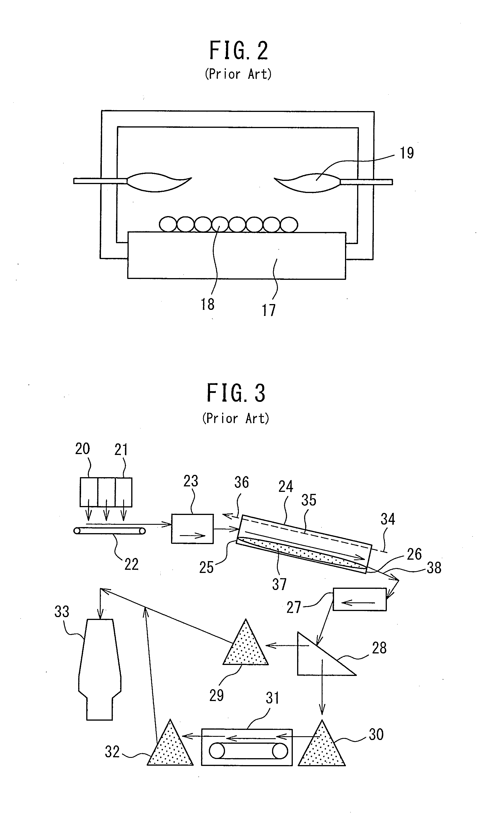
TECHNICAL FIELD[0001]The present invention relates to an apparatus for and method of production of reduced iron for reclaiming metallic iron from dust which is generated at an integrated ironmaking plant.BACKGROUND ART[0002]The dust which is generated at an integrated ironmaking plant (ironmaking dust) contains a large amount of metallic iron. In particular, the dust in exhaust gas which is generated at a top blown converter (converter dust) reaches 10 kg / t steel in terms of the amount of dust generated per ton of iron produced, so is recovered and recycled as a source of iron. Converter dust is present in high temperature converter exhaust gas, so usually is recovered by wet dust collection. Wet collected converter dust is recovered by a thickener and treated to dehydrate it so that the moisture content becomes 20 to 28%. Even if dehydrated, with this level of moisture content, a muddy state is exhibited, so usually this is called “converter sludge”.[0003]Converter sludge is muddy ...

Claims


Application Information

Patent Timeline
IPC IPC(8): C21B11/06F27B7/42F27B7/36C21B11/10F27B7/34F27B7/33F27B7/10F27B7/08
CPCF27B7/36F27M2001/023F27M2001/04F27M2003/165C21B11/10C21B11/06F27M2001/16F27B7/34F27B7/33F27B7/42F27B7/08F27B7/10C21B2100/02C21B13/105C22B1/216C22B1/2406C22B1/248C22B7/02F27B7/02F27D17/004F27D17/008Y02P10/134Y02P10/20C21B2100/44
Inventor UEKAWA, SEITANABEKURA, KAZUNORI
Owner TETSUGEN CO LTD
Learn More