
Compact device for detecting at least one acceleration and one speed of rotation

a compact device and acceleration technology, applied in the direction of acceleration measurement using interia force, devices using electric/magnetic means, instruments, etc., can solve the problems of complex data processing, long manufacture time, complex detection of all the axes of detection and excitation, etc., and achieve the effect of simple electronics and easy production

Active Publication Date: 2015-01-15
COMMISSARIAT A LENERGIE ATOMIQUE ET AUX ENERGIES ALTERNATIVES
View PDF1 Cites 13 Cited by
  • Summary
  • Abstract
  • Description
  • Claims
  • Application Information

AI Technical Summary

Benefits of technology

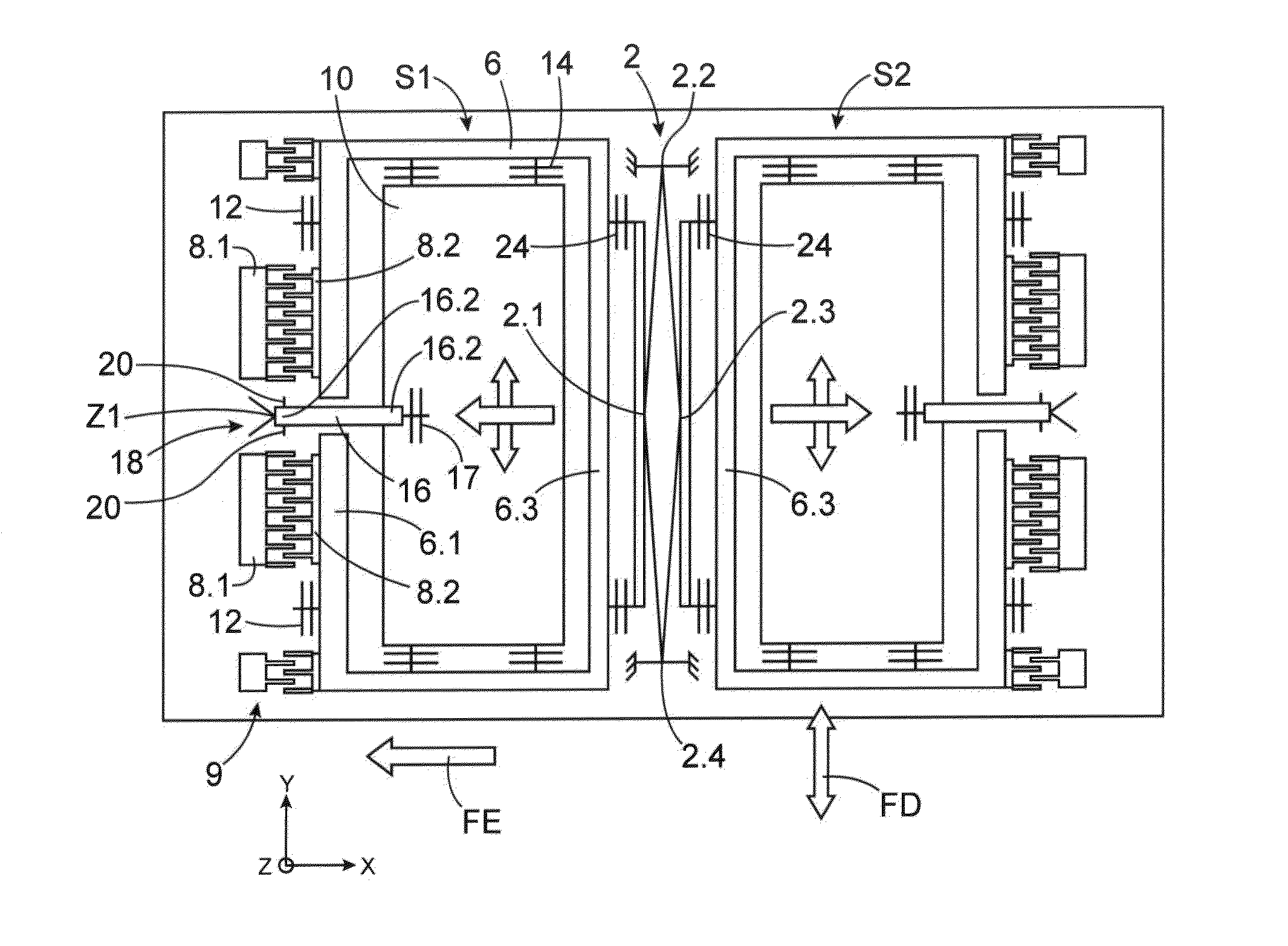
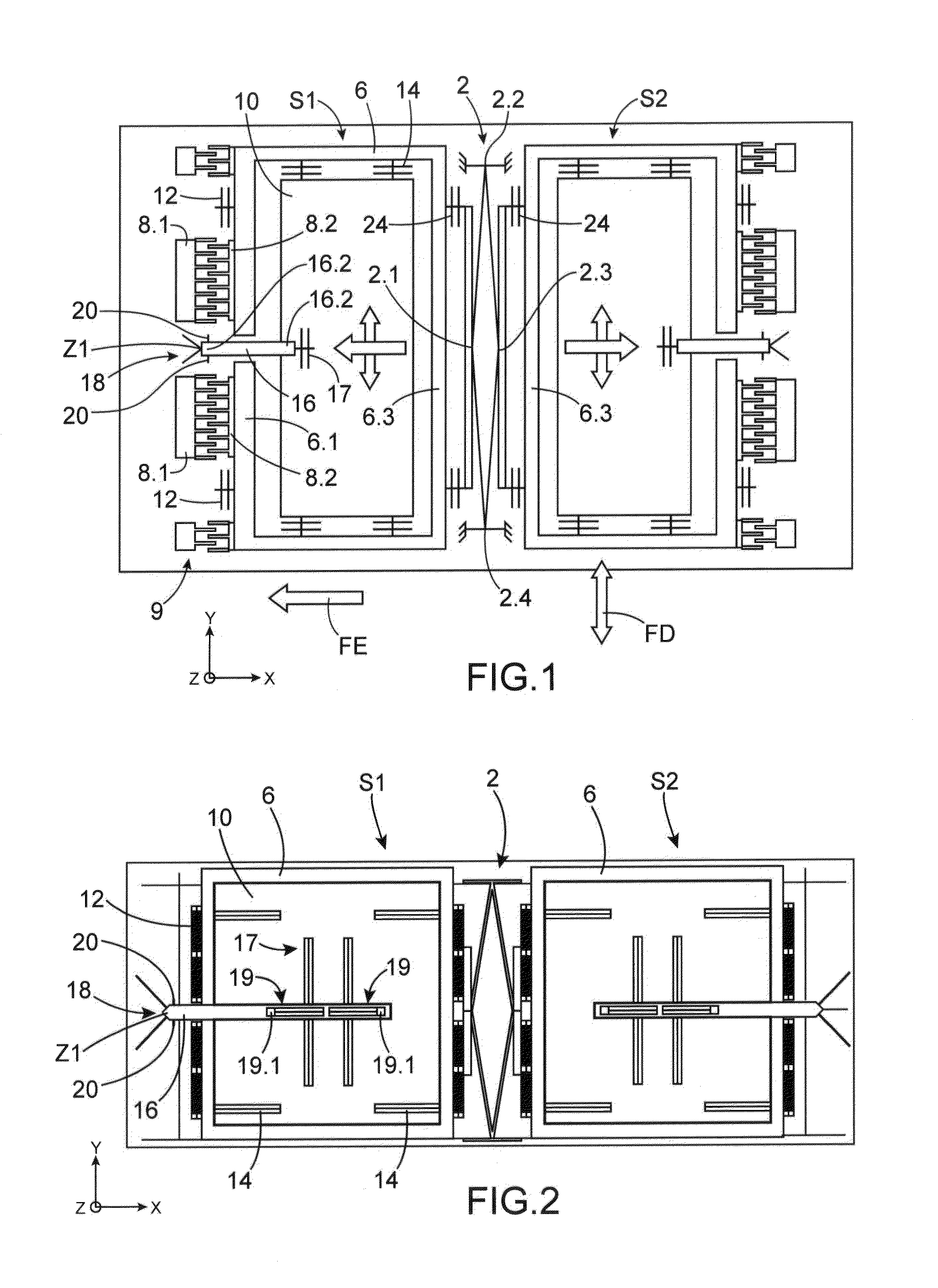
The present invention provides an inertial unit that can measure acceleration and rotational speed in three directions. The unit is compact and has a simplified electronics design, making it easy and cost-effective to manufacture. The invention reduces the cost of the device by using the same inertial masses for measuring both acceleration and speed of rotation. The detecting means can also be projected outwardly from the masses, allowing for out-of-plane measurements. Additionally, the invention provides an increased sensitivity by using a pivot connection for the detecting element. By combining multiple units, accelerations and speeds of rotation can be measured in multiple space directions, while using the same excitation loop for power consumption reduction.

Problems solved by technology

On the one hand, this unit is made in the volume technology, which makes its manufacture long and expensive.
On the other hand, the detection of all the axes of detection and the excitation are intricate.
The data processing is thus complex and there is a high risk of introducing errors, this being all the higher that the air-gap variation capacity detection is non-linear, this non-linearity being amplified when the movements are of a strong amplitude, which is the case of the excitation movements.
Further, the measurement accuracy is all the higher that the capacitive air-gap is low, but the actuation requires high air-gaps to achieve significant amplitudes.
The implementation of implanted gauges has the drawback of having a great sensitivity to the stress.

Method used


Image

  • Compact device for detecting at least one acceleration and one speed of rotation
  • Compact device for detecting at least one acceleration and one speed of rotation
  • Compact device for detecting at least one acceleration and one speed of rotation

Examples


Embodiment Construction

[0071]In the description that follows, the terms “sensor”, “detecting device” and “inertial unit” are used interchangeably.

[0072]The orientations of directions X, Y and Z are identical throughout the figures.

[0073]By way of example, the axes X, Y and Z are defined as follows:[0074]the axes X and Y define the plane of the inertial unit, in the representations, these are contained in the sheet plane, direction X is the horizontal direction, direction Y is the vertical direction and[0075]the axis Z is perpendicular to the unit plane, and to the sheet plane in the representations.

[0076]It is reminded that when:[0077]the direction of excitation is direction X and the direction of detection is direction Z, the acceleration is detected along direction Z and the speed of rotation along direction Y,[0078]the direction of excitation is direction X and the direction of detection is direction Y, the acceleration is detected along direction Y and the speed of rotation along direction Z,[0079]the...


PUM


Abstract

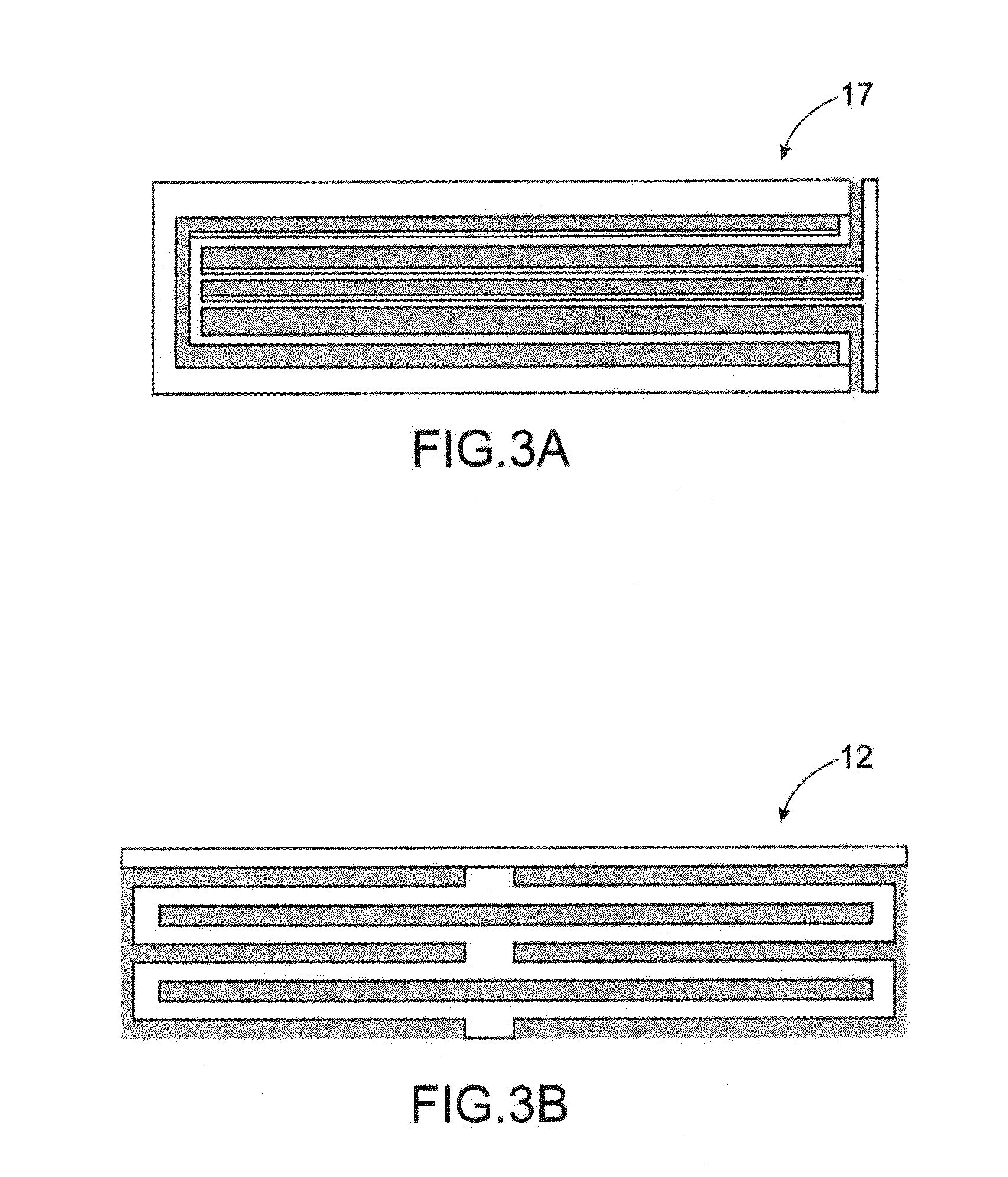
A device for detecting an acceleration in one direction and a speed of rotation along one direction, including a support and two structures mechanically coupled to each other in opposite phase and suspended relative to the support, each of the structures including: an excitation mass; an excitation mechanism configured to move the excitation mass in a given direction; an inertial mass suspended to the excitation mass; a detector connected to the inertial mass to be displaced by same, and the detector connected to the support; a mechanism for detecting displacement of the inertial mass; and a controller controlling the excitation mechanism and processing signals delivered by the detecting mechanism.

Description

TECHNICAL FIELD AND PRIOR ART[0001]The present invention relates to a device for detecting at least one acceleration and one speed of rotation having a compact design and simplified electronics.[0002]There are inertial units having five axes of detection, three axes in acceleration and two axes in rotation. Such a unit is described in document Y. Watanabe et al, “Five axis motion sensor with electrostatic drive and capacitive detection fabricated with silicon bulk micromachining”, Sensors and Actuators A, Vol 97-98, p 109-115, 2002. On the one hand, this unit is made in the volume technology, which makes its manufacture long and expensive. On the other hand, the detection of all the axes of detection and the excitation are intricate. The data processing is thus complex and there is a high risk of introducing errors, this being all the higher that the air-gap variation capacity detection is non-linear, this non-linearity being amplified when the movements are of a strong amplitude, w...

Claims


Application Information

Patent Timeline
Patent Type & Authority Applications(United States)
IPC IPC(8): G01P3/44G01C19/5747G01P15/12
CPCG01C19/5747G01P3/44G01P15/123
Inventor DEIMERLY, YANNICK
Owner COMMISSARIAT A LENERGIE ATOMIQUE ET AUX ENERGIES ALTERNATIVES
Learn More