Terminal, base station, transmission method, and reception method

a transmission method and terminal technology, applied in the direction of wireless communication, transmission path division, wireless commuication services, etc., can solve problems such as interference to the terminal, and achieve the effect of preventing deterioration of throughput and ensuring the accuracy of csi measurement results in the terminal

Active Publication Date: 2015-01-08
PANASONIC INTELLECTUAL PROPERTY CORP OF AMERICA
View PDF2 Cites 15 Cited by
  • Summary
  • Abstract
  • Description
  • Claims
  • Application Information

AI Technical Summary

Benefits of technology

The invention helps to accurately measure the quality of a signal in a mobile device and prevent the network from slowing down.

Problems solved by technology

That is, a signal from a TP that stores no data intended for the terminal (e.g., TP adjacent to a TP to which the terminal is connected) is regarded as interference to the terminal.

Method used


Image

  • Terminal, base station, transmission method, and reception method
  • Terminal, base station, transmission method, and reception method
  • Terminal, base station, transmission method, and reception method

Examples


embodiment 1

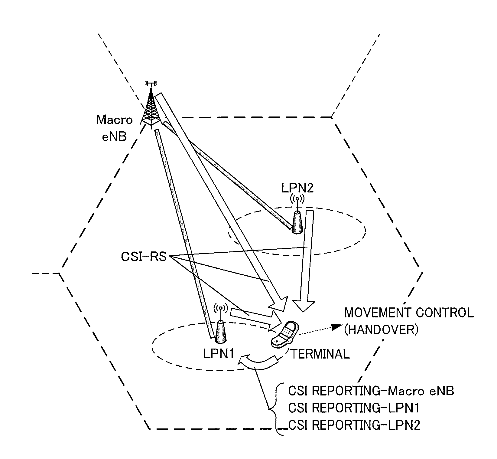
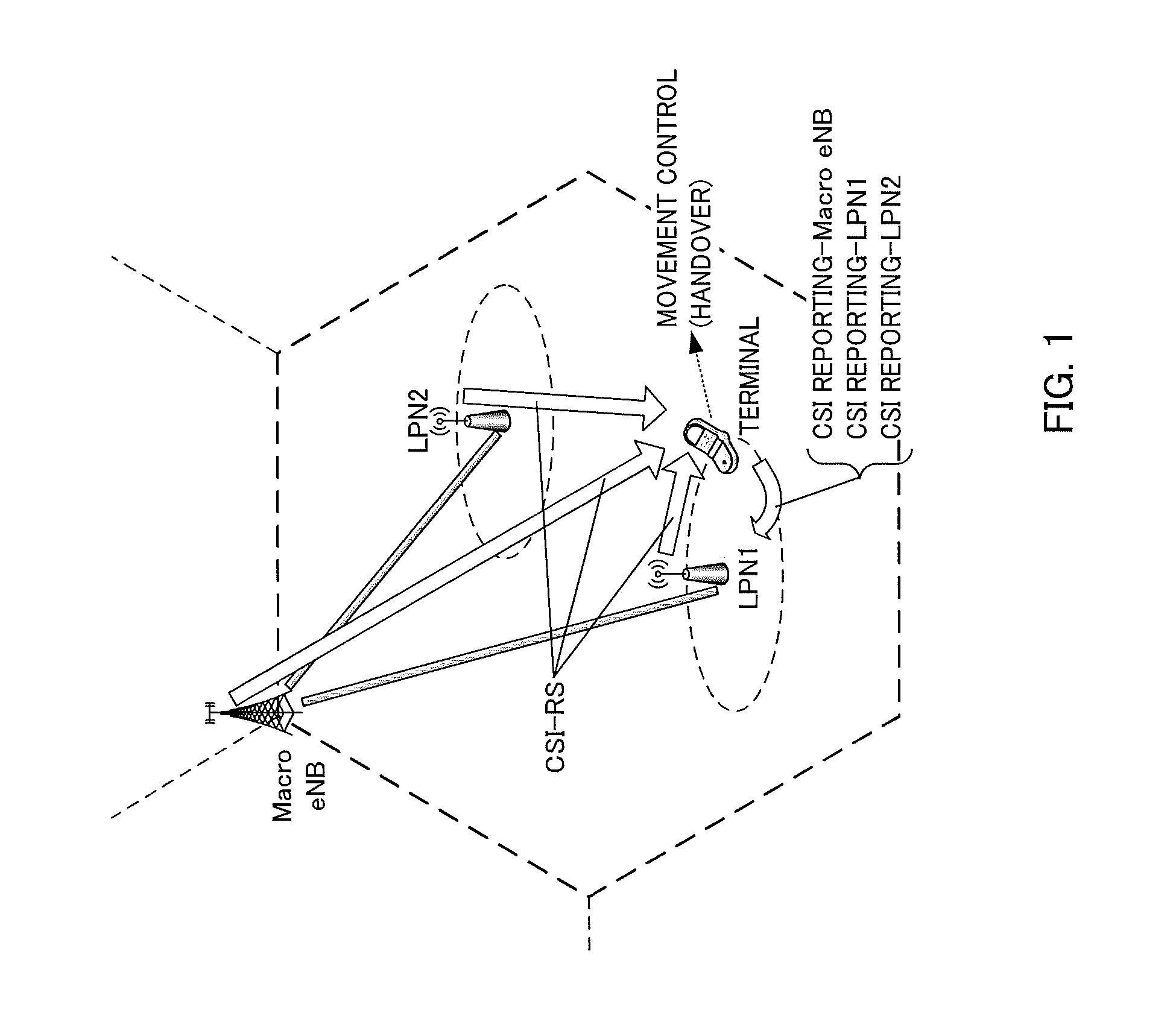
Overview of Communication System

[0069]A communication system according to Embodiment 1 of the present invention includes base station 100 and terminals 200. Base station 100 is an LTE-A compliant base station and terminals 200 are LTE-A compliant terminals.

[0070]FIG. 10 is a main configuration diagram of base station 100 according to Embodiment 1 of the present invention. In base station 100, configuration section 101 configures a plurality of TPs for terminal 200 and reception processing section 108 receives CSI (channel information) of a plurality of TPs in subframes other than a subframe (second subframe) identified based on a paging subframe (first subframe) configured for each of a plurality of TPs but does not receive CSI in the identified subframe.

[0071]FIG. 11 is a main configuration diagram of terminal 200 according to Embodiment 1 of the present invention. In terminal 200, reception processing section 203 receives CSI-RSs (reference signals) transmitted from a plurality of...

embodiment 2

[0120]Since a base station and a terminal according to the present embodiment have basic configurations common to those of base station 100 and terminal 200 according to Embodiment 1, the base station and terminal will be described with reference to FIGS. 12 and 13.

[0121]In base station 100 according to the present embodiment, configuration section 101 generates “partial TP information” indicating at least one or some transmission points among a plurality of TP candidates included in TP candidate information for CSI reporting target terminal 200 in addition to the operation of Embodiment 1. For example, configuration section 101 configures TPs (CoMP measurement set) to be targets of CoMP control among a plurality of TP candidates as the TPs included in the partial TP information. Configuration section 101 generates paging subframe information for each TP included in the partial TP information for CSI reporting target terminal 200.

[0122]As described above, partial TP information gene...


PUM


Abstract

Provided is a terminal whereby the accuracy of CSI measurement results in the terminal can be assured, and declines in throughput prevented. In this terminal, a reception processor (203) receives reference signals respectively transmitted from a plurality of transmission points. A CSI generator (206) identifies a second subframe on the basis of a first subframe respectively established for each of the plurality of transmission points, and using the reference signals from the plurality of transmission points, generates channel information in a subframe other than the second subframe, without generating channel information in the second subframe. A transmission signal former (208) transmits the generated channel information.

Description

TECHNICAL FIELD[0001]The present invention relates to a terminal, a base station, a transmission method and a reception method.BACKGROUND ART[0002]The 3rd Generation Partnership Project Radio Access Network Long Term Evolution (hereinafter, referred to as “LTE”) and LTE-Advanced which is an evolved version of LTE (hereinafter, referred to as “LTE-A”) employ orthogonal frequency division multiple access (OFDM) scheme for the downlink communication scheme.[0003]For frequency scheduling and link adaptation in OFDMA, each terminal (which may also be called “UE (User Equipment)”) measures channel information (CSI: channel state information) and reports the channel information (CSI measurement result) to a base station (which may also be called “eNB”). On the other hand, the base station performs appropriate resource allocation for the terminal using channel information (CSI measurement result).[0004]In LTE, CSI is measured using a cell-specific reference signal (CRS). CRSs are transmitte...

Claims


Application Information

Patent Timeline
IPC IPC(8): H04L5/00
CPCH04L5/0053H04W24/10H04L5/001H04L5/0048H04L5/0057H04L5/0087H04L5/0092H04L5/0035
Inventor HOSHINO, MASAYUKITAMURA, TAKASHI
Owner PANASONIC INTELLECTUAL PROPERTY CORP OF AMERICA
Why Eureka
Try Eureka