Wheel position detecting device and tire pressure detecting apparatus having the same
a technology of position detecting device and tire pressure detecting apparatus, which is applied in the direction of pressure difference measurement between multiple valves, digital computer details, instruments, etc., can solve the problems of inability to specify the wheel position, difficulty in properly counting the tooth number in the low speed region, and difficulty in properly specifying the position of the wheel
- Summary
- Abstract
- Description
- Claims
- Application Information
AI Technical Summary
Benefits of technology
Problems solved by technology
Method used
Image
Examples
first embodiment
[0036]A first embodiment will be described with reference to FIGS. 1 to 8D.
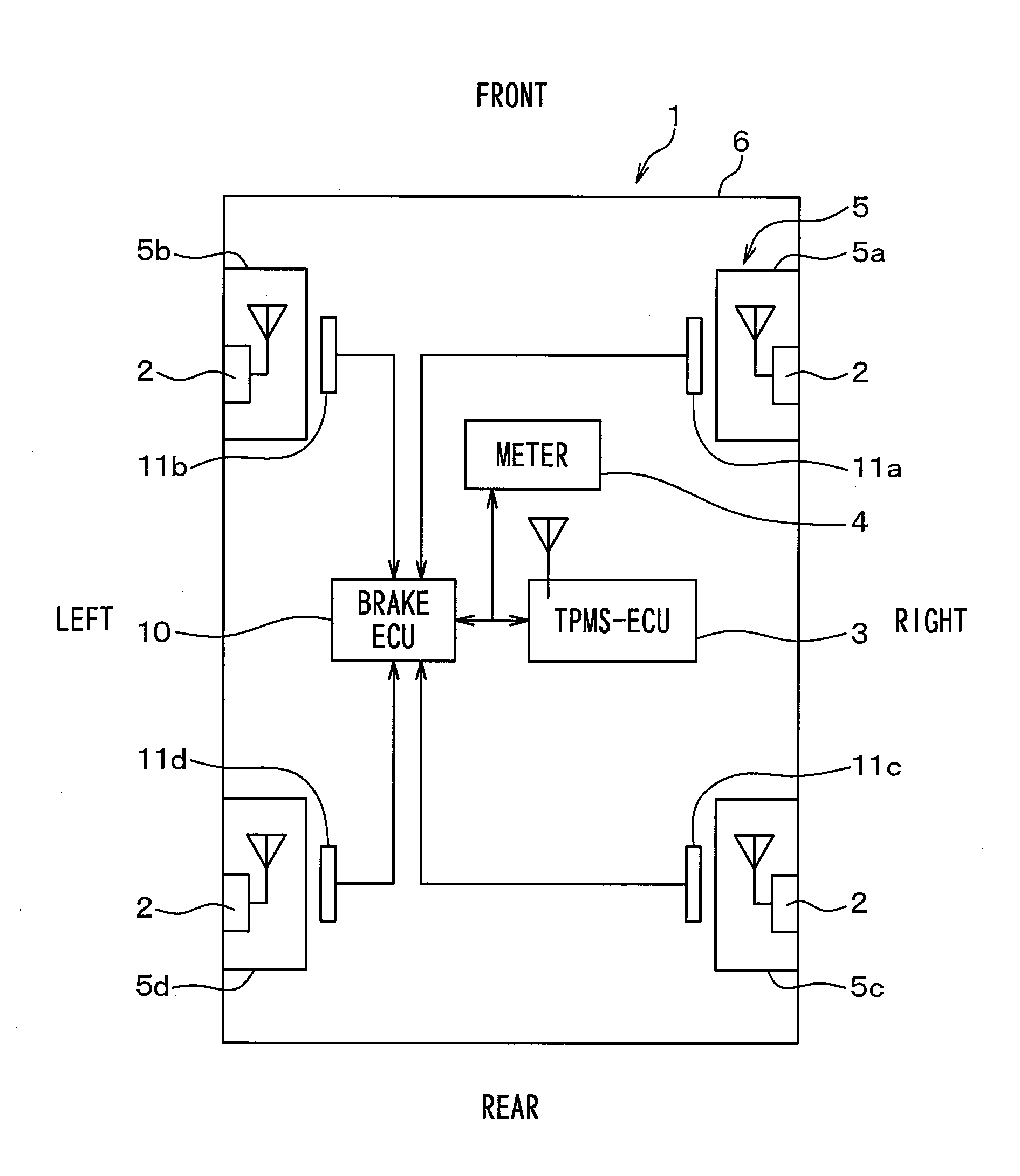
[0037]FIG. 1 is a schematic diagram illustrating an overall structure of a wheel position detecting device and an overall structure of a tire pressure detecting apparatus in a vehicle 1. In FIG. 1, an upward direction corresponds to a frontward direction of the vehicle 1, and a downward direction corresponds to a rearward direction of the vehicle 1. The tire pressure detecting apparatus according to the present embodiment will be described with reference to FIG. 1.
[0038]The tire pressure detecting apparatus is equipped to the vehicle 1. The tire pressure detecting apparatus includes a transmitter 2, a tire pressure monitoring system electronic control unit (hereinafter referred to as the TPMS-ECU) 3, and a meter 4. The TPMS-ECU 3 serves as a receiver.
[0039]The wheel position detecting device uses the transmitter 2 and the TPMS-ECU 3, which are included in the tire pressure detecting apparatus. The wheel posit...
second embodiment
[0123]A second embodiment of the present disclosure will be hereinafter described. In the second embodiment, a way of transmitting the frame from the transmitter 2 is different from that of the first embodiment. Other features are the same as the first embodiment. Therefore, the feature different from the first embodiment will be mainly described.
[0124]In the first embodiment, the transmitter 2 transmits the frame each time the acceleration sensor 22 is at a certain angular position. That is, the transmission angular position of the transmitter 2 is fixed. In the present embodiment, on the other hand, the transmission angular position is changed each time that the vehicle 1 stops.
[0125]In a case where the transmission angular position of the transmitter 2 is fixed, if the transmission angular position coincides with a position where the frame is less likely to reach the TPMS-ECU 3, such as a Null, it will be difficult that the TPMS-ECU 3 receives the frame every time the frame is tr...
PUM
| Property | Measurement | Unit |
|---|---|---|
| speed | aaaaa | aaaaa |
| reception angle | aaaaa | aaaaa |
| reception angle | aaaaa | aaaaa |
Abstract
Description
Claims
Application Information
 - R&D
- Intellectual Property
- Life Sciences
- Materials
- Tech Scout
- Unparalleled Data Quality
- Higher Quality Content
- 60% Fewer Hallucinations
Browse by: Latest US Patents, China's latest patents, Technical Efficacy Thesaurus, Application Domain, Technology Topic, Popular Technical Reports.
© 2025 PatSnap. All rights reserved.Legal|Privacy policy|Modern Slavery Act Transparency Statement|Sitemap|About US| Contact US: help@patsnap.com


