Circuit configuration for radar applications

a circuit configuration and radar technology, applied in the field of circuit configuration for radar applications, can solve the problems of antenna structure apertures that cannot be implemented, and achieve the effect of high level of consistency of reference signals

Inactive Publication Date: 2015-01-01
ROBERT BOSCH GMBH
View PDF28 Cites 9 Cited by
  • Summary
  • Abstract
  • Description
  • Claims
  • Application Information

AI Technical Summary

Benefits of technology

[0021]In one exemplary embodiment, the circuit configuration has an oscillator situated on the printed board for generating a reference signal, in particular a common reference signal. The reference signal may be fed to the phase-locked loops via the printed board. The oscillator may be a crystal oscillator. For example, the oscillator is an oscillator circuit including an oscillating crystal. This makes it possible to achieve a high level of consistency of the reference signal.
[0022]In one exemplary embodiment, multiple semiconductor modules are situated in a regular pattern in one row on the printed board. This makes it possible to achieve a locally distributed positioning of the antenna elements integrated into the semiconductor modules.

Problems solved by technology

For the design of automotive radar sensors having a long range, apertures of the antenna structures are needed, which cannot be implemented within such a semiconductor module due to the limitation of the size of an eWLB semiconductor module.

Method used


Image

  • Circuit configuration for radar applications
  • Circuit configuration for radar applications
  • Circuit configuration for radar applications

Examples


Embodiment Construction

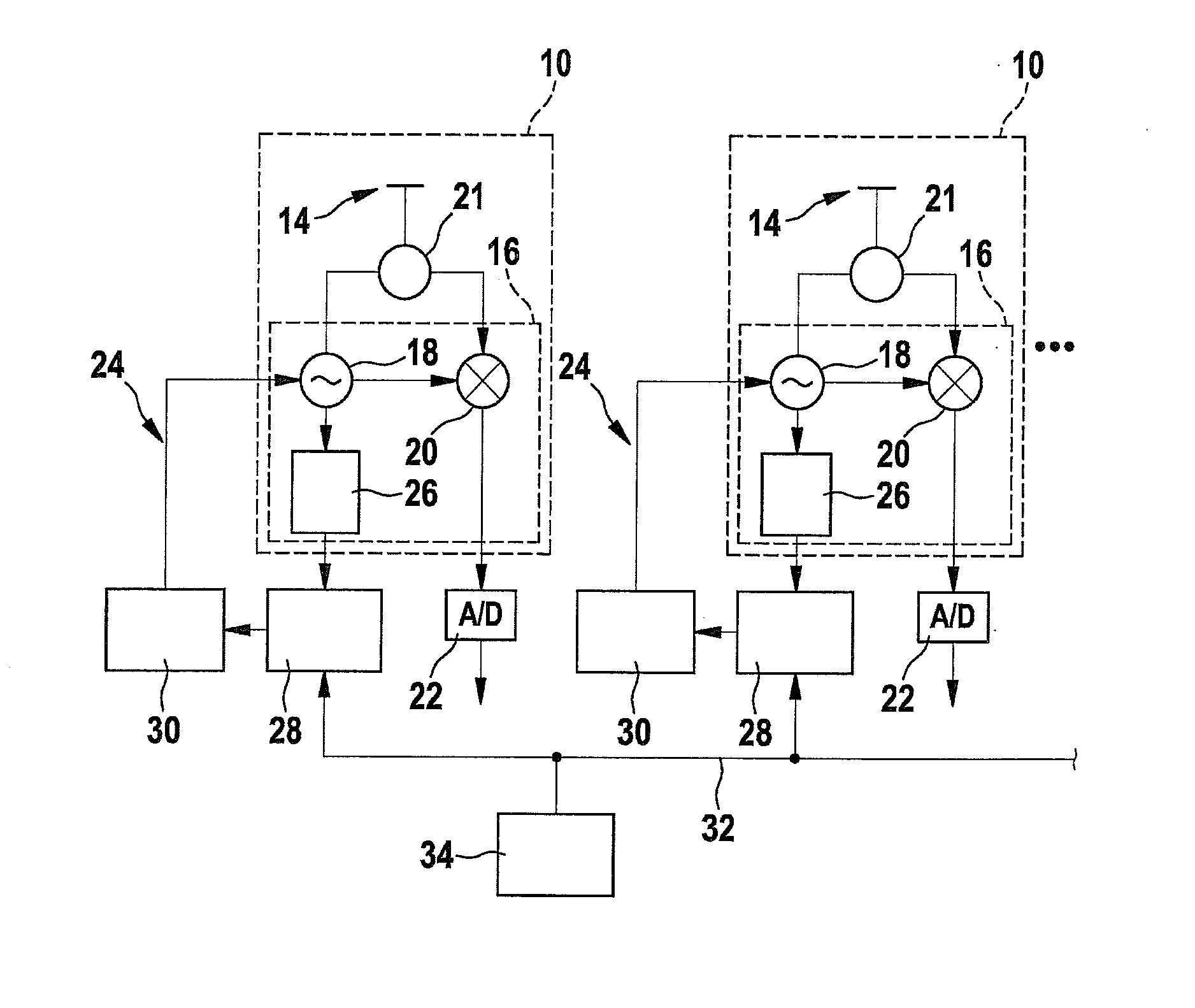
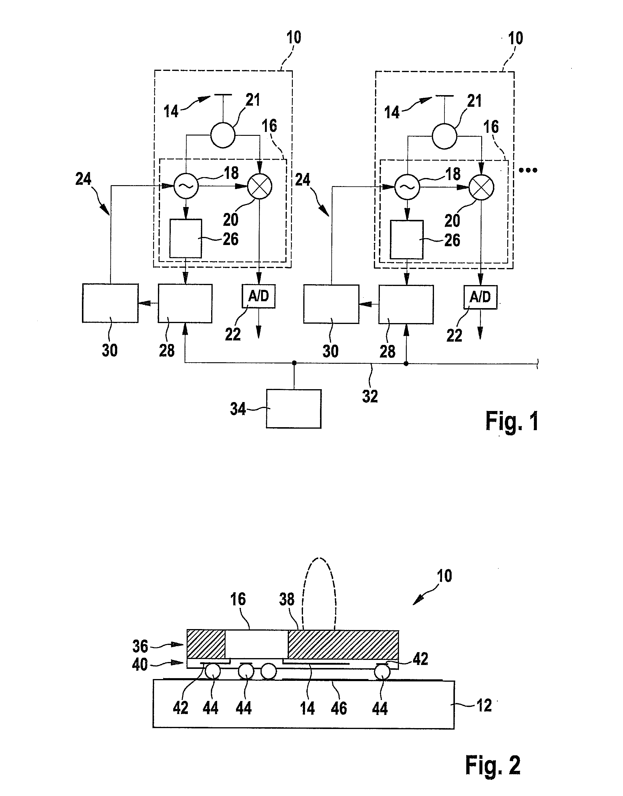
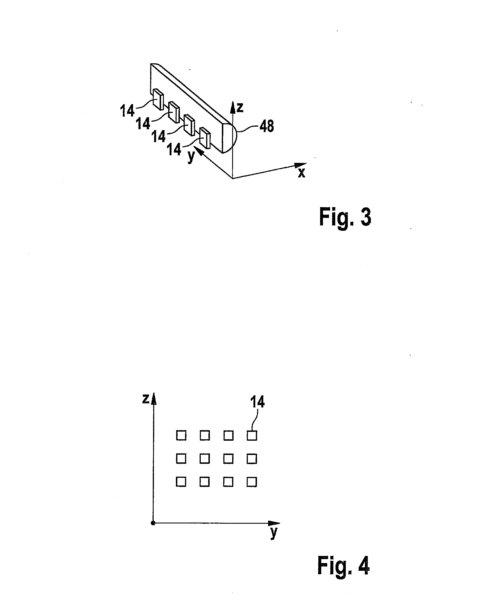
[0029]FIG. 1 schematically shows a circuit configuration having multiple semiconductor modules 10, one of which is shown in cross section in FIG. 2. Semiconductor modules 10 are, for example, mounted in one row on a printed board 12. In FIG. 1, two of semiconductor modules 10 are shown as examples.

[0030]Each of semiconductor modules 10 includes an integrated antenna element 14 and an integrated circuit16 in the form of a semiconductor chip. The antenna element is, for example, a patch element which is used for transmitting and receiving a radar signal in the example shown. Integrated circuit 16 includes the HF component of a transmission and reception circuit and is connected to antenna element 14.

[0031]In particular, integrated circuit 16 includes an HF oscillator 18 for generating a radar signal for emission by antenna element 14. Furthermore, in a known manner, integrated circuit 16 includes a mixer 20 for mixing the received radar signal with the transmitted signal. Antenna elem...


PUM


Abstract

A circuit configuration for radar applications having a printed board and semiconductor modules mounted on it, each of the semiconductor modules including an integrated circuit, a rewiring layer for connecting the integrated circuit to the printed board and at least one antenna element integrated into the semiconductor module and connected to the integrated circuit for transmitting and/or receiving radar signals, the integrated circuit including at least one HF oscillator and a frequency splitter connected to the HF oscillator, the circuit configuration including phase-locked loops for controlling the HF oscillators, each of the phase-locked loops having the frequency splitter and a phase detector for comparing a split-frequency signal of the HF oscillator with a reference signal, and the reference signals may be fed to the phase-locked loops via the printed board.

Description

FIELD OF THE INVENTION[0001]The present invention relates to a circuit configuration for radar applications, in particular motor vehicle radar applications. The present invention further relates to a radar sensor having such a circuit configuration as well as a motor vehicle radar system having a circuit configuration of this type.BACKGROUND INFORMATION[0002]Radar sensors are used for measuring the distance and / or speed of objects. In particular, radar systems are known in which speeds and distances of multiple objects are detected simultaneously. For example, vehicle speed regulators are known for motor vehicles having a radar system for locating a preceding vehicle and for measuring the distance to same. Such a distance regulating system is also referred to as an ACC (adaptive cruise control) system.[0003]Radar systems are known which form distributor networks to antenna elements on HF substrates.[0004]German patent document DE 10 2007 051 875 A1 discusses an HF assembly having a ...

Claims


Application Information

Patent Timeline
Patent Type & Authority Applications(United States)
IPC IPC(8): G01S7/02G01S13/931
CPCG01S7/02G01S7/032G01S13/931G01S2013/9321H01L24/19H01L2924/18162H01L2224/12105H01L2924/181H01L2223/6677H01L2924/00
Inventor BINZER, THOMASBRUEGGEMANN, OLIVERWALDSCHMIDT, CHRISTIANSTEINBUCH, DIRK
Owner ROBERT BOSCH GMBH
Why Eureka
Try Eureka