Brake system for vehicle designed to produce braking force in case of loss of electric power
- Summary
- Abstract
- Description
- Claims
- Application Information
AI Technical Summary
Benefits of technology
Problems solved by technology
Method used
Image
Examples
second embodiment
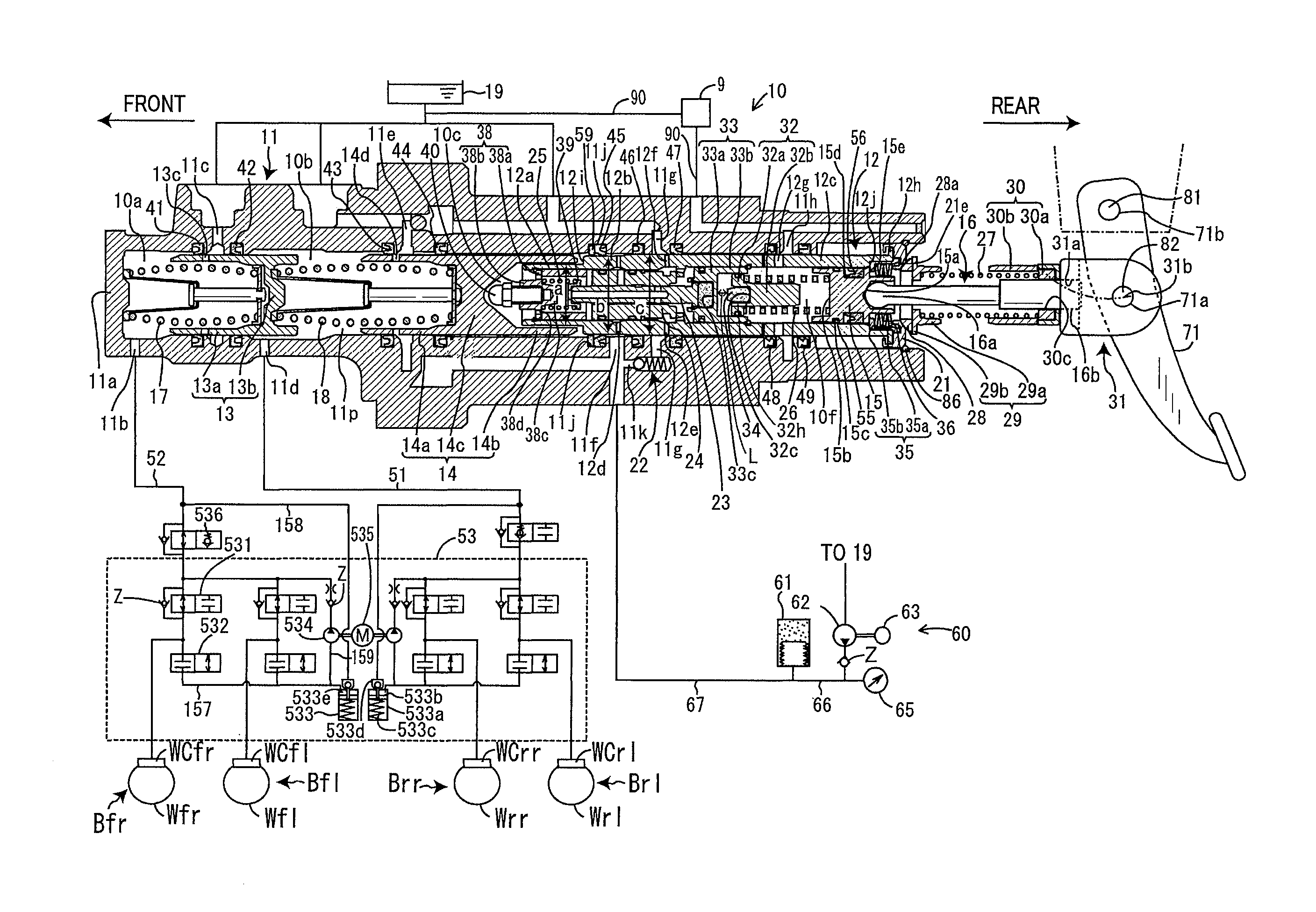
[0168]The brake system B of the second embodiment will be described below which is different from the one in the first embodiment only in structure of the power loss fail-safe unit 9.
[0169]Specifically, the brake system B of this embodiment is, as illustrated in FIG. 13, equipped with a power loss fail-safe unit 9A. The same reference numbers, as employed in the first embodiment, will refer to the same parts, and explanation thereof in detail will be omitted here.
[0170]The power loss fail-safe unit 9A is equipped with an electromagnetic valve 91, a pressure regulator 96 working as a stroke chamber pressure regulator, a check valve 93, and pipes 95, 97, and 98. The pipe 98 connects at an end thereof with a portion of the pipe 90 which extends between one of ends of the electromagnetic valve 91 and the seventh port 11h and at the other end thereof with one of ends of the pressure regulator 96. The pipe 97 connects at an end thereof with the other end of the pressure regulator 96 and a...
PUM
 Abstract
Description
Claims
Application Information
 - R&D
- Intellectual Property
- Life Sciences
- Materials
- Tech Scout
- Unparalleled Data Quality
- Higher Quality Content
- 60% Fewer Hallucinations
Browse by: Latest US Patents, China's latest patents, Technical Efficacy Thesaurus, Application Domain, Technology Topic, Popular Technical Reports.
© 2025 PatSnap. All rights reserved.Legal|Privacy policy|Modern Slavery Act Transparency Statement|Sitemap|About US| Contact US: help@patsnap.com


