
System and method for a fuel nozzle

a fuel nozzle and system technology, applied in the ignition of turbine/propulsion engine, borehole/well accessories, lighting and heating apparatus, etc., can solve the problems of increasing carbon monoxide emissions and/or reducing combustion efficiency, gas turbine engines typically consume a vast amount of air, and releasing a considerable amount of exhaust gas into the atmospher

Active Publication Date: 2015-01-01
GENERAL ELECTRIC CO
View PDF7 Cites 38 Cited by
  • Summary
  • Abstract
  • Description
  • Claims
  • Application Information

AI Technical Summary

Benefits of technology

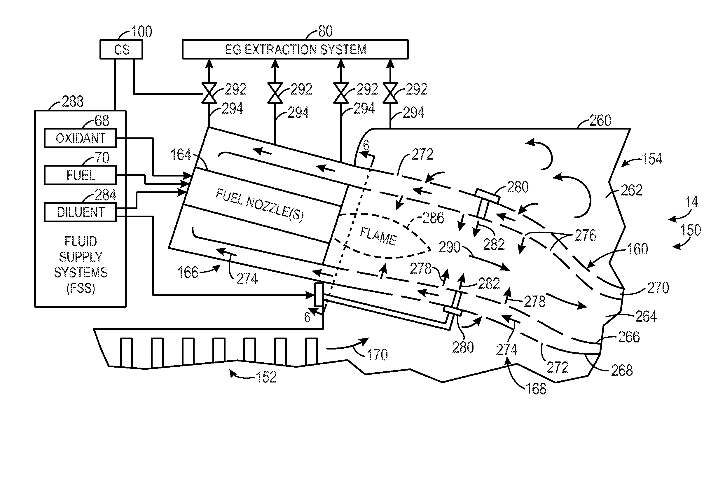
The patent describes a system and method for injecting oxidant and fuel into a gas turbine engine for improved combustion. The system includes a diffusion fuel nozzle with multiple openings that inject oxidant and fuel in different directions, creating a swirling motion that enhances ignition and mixing in the combustor. The method involves injecting the oxidant and fuel into the combustor through the diffusion fuel nozzle, resulting in improved combustion efficiency and reduced emissions. The technical effects of this system and method include improved engine performance and efficiency, reduced emissions, and improved ignition and mixing in the combustor.

Problems solved by technology

Unfortunately, insufficient mixing of the fuel and oxidant can result in increased carbon monoxide emissions and / or decreased combustion efficiency.
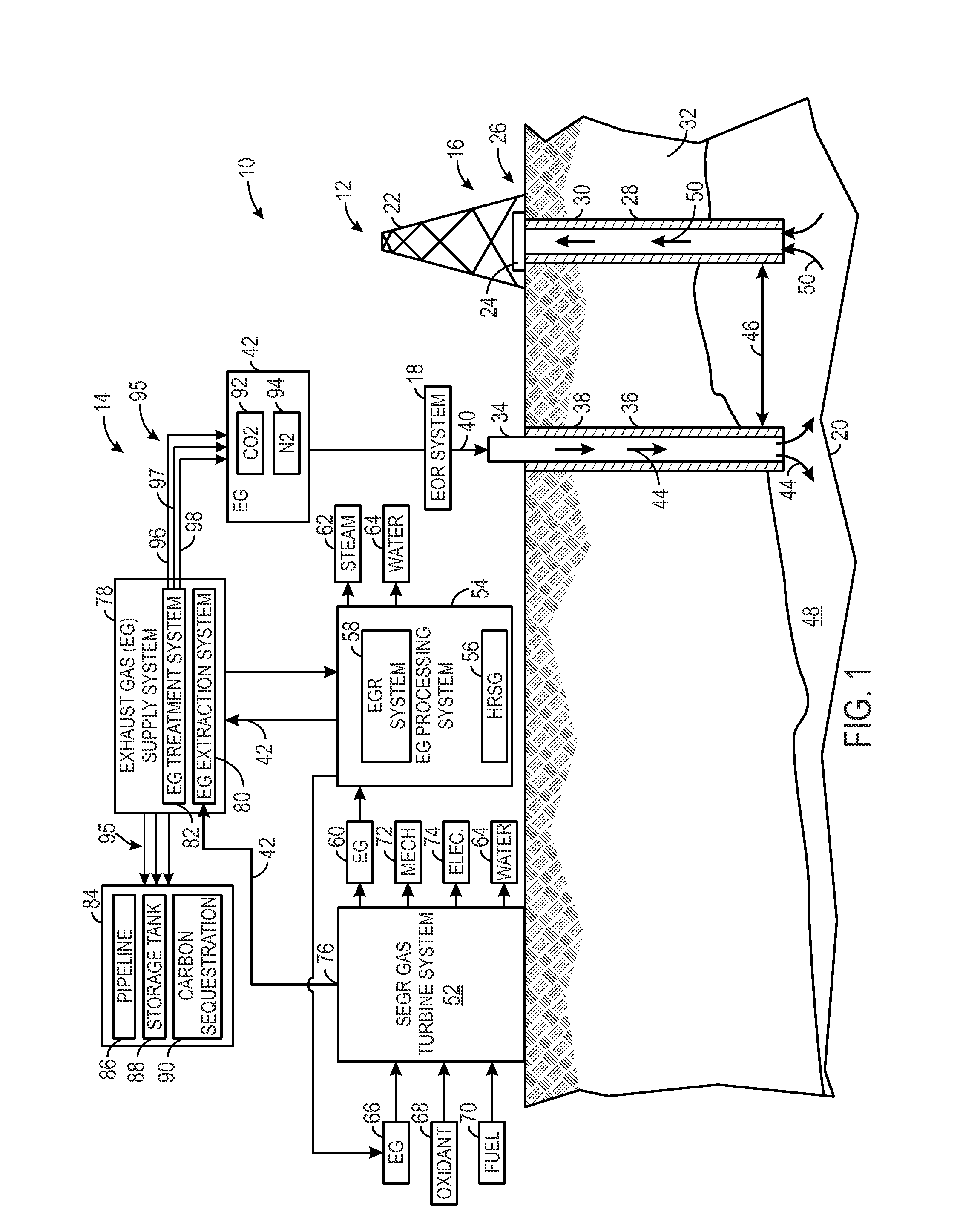
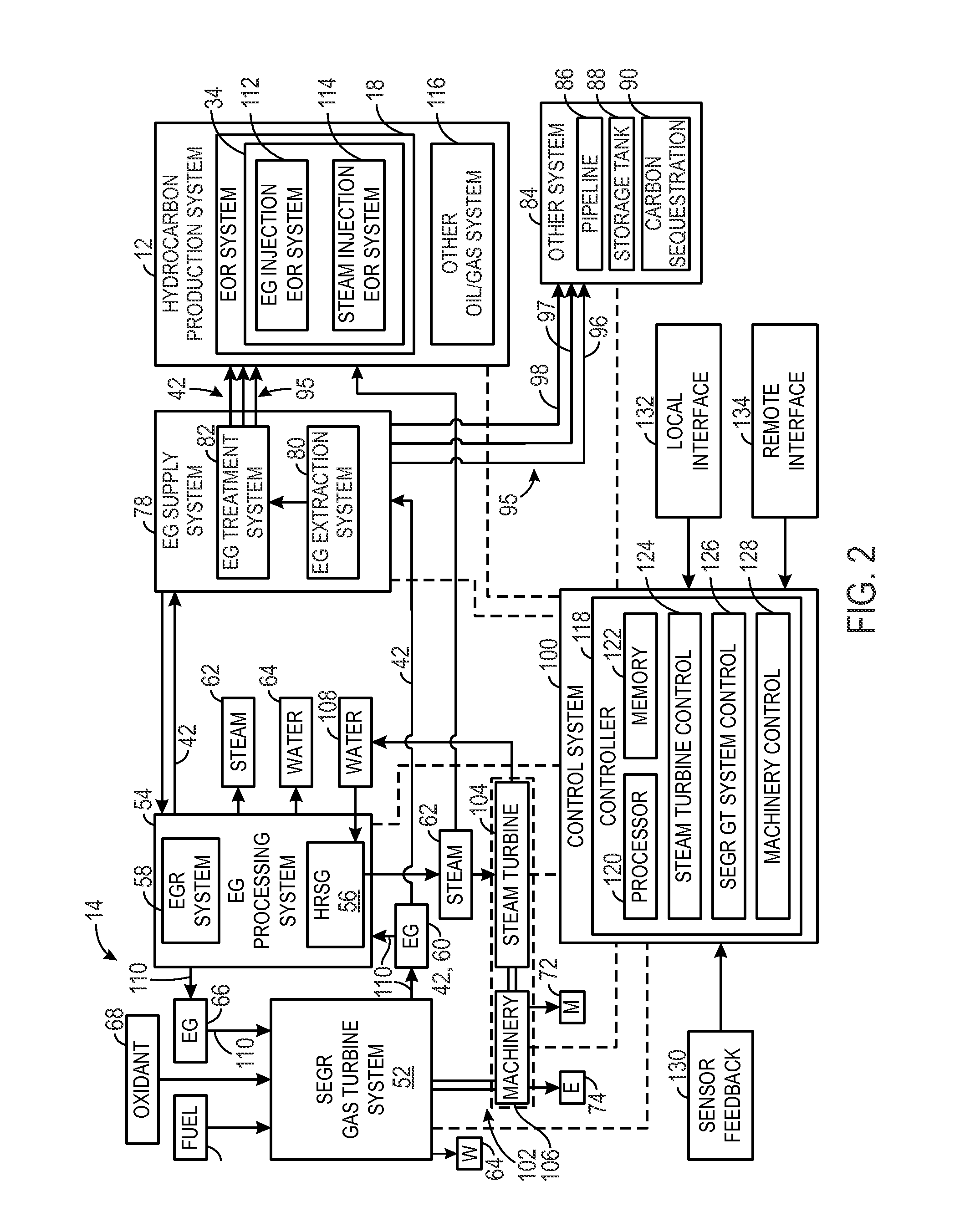
Furthermore, gas turbine engines typically consume a vast amount of air as the oxidant, and output a considerable amount of exhaust gas into the atmosphere.
In other words, the exhaust gas is typically wasted as a byproduct of the gas turbine operation.

Method used


Image

  • System and method for a fuel nozzle
  • System and method for a fuel nozzle
  • System and method for a fuel nozzle

Examples


embodiment 1

[0091]A turbine combustor, comprising: an oxidant compressor; and a gas turbine engine, comprising: a combustor section having a turbine combustor, wherein the turbine combustor comprises: a plurality of diffusion fuel nozzles, wherein each of the plurality of diffusion fuel nozzles comprises: a first oxidant conduit configured to inject a first oxidant through a plurality of first oxidant openings, wherein the plurality of first oxidant openings are configured to impart swirling motion to the first oxidant in a first rotational direction; a first fuel conduit configured to inject a first fuel through a plurality of first fuel openings, wherein the first fuel conduit surrounds the first oxidant conduit, and the plurality of first fuel openings are configured to impart swirling motion to the first fuel in a second rotational direction; and a second oxidant conduit configured to inject a second oxidant through a plurality of second oxidant openings, wherein the second oxidant conduit ...

embodiment 2

[0092]The system of embodiment 1, wherein a first oxidant wall of the first oxidant conduit is disposed at a first radial distance from a central axis of the diffusion fuel nozzle, a first fuel wall of the first fuel conduit is disposed at a second radial distance from the central axis, and a second oxidant wall of the second oxidant conduit is disposed at a third radial distance from the central axis, wherein the second radial distance is greater than the first radial distance and the third radial distance is greater than the second radial distance.

embodiment 3

[0093]The system defined in any preceding embodiment, wherein the second rotational direction is opposite from the first and third rotational directions.


PUM


Abstract

A system includes an oxidant compressor and a gas turbine engine turbine, which includes a turbine combustor, a turbine, and an exhaust gas compressor. The turbine combustor includes a plurality of diffusion fuel nozzles, each including a first oxidant conduit configured to inject a first oxidant through a plurality of first oxidant openings configured to impart swirling motion to the first oxidant in a first rotational direction, a first fuel conduit configured to inject a first fuel through a plurality of first fuel openings configured to impart swirling motion to the first fuel in a second rotational direction, and a second oxidant conduit configured to inject a second oxidant through a plurality of second oxidant openings configured to impart swirling motion to the second oxidant in a third rotational direction. The first fuel conduit surrounds the first oxidant conduit and the second oxidant conduit surrounds the first fuel conduit.

Description

CROSS-REFERENCE TO RELATED APPLICATIONS[0001]This application claims priority to and benefit of U.S. Provisional Patent Application No. 61 / 841,201, entitled “SYSTEM AND METHOD FOR A FUEL NOZZLE,” filed on Jun. 28, 2013, which is hereby incorporated by reference in its entirety for all purposes.BACKGROUND[0002]The subject matter disclosed herein relates to gas turbine engines, and more specifically, to systems and methods for fuel nozzles of gas turbine engines.[0003]Gas turbine engines are used in a wide variety of applications, such as power generation, aircraft, and various machinery. Gas turbine engines generally combust a fuel with an oxidant (e.g., air) in a combustor section to generate hot combustion products, which then drive one or more turbine stages of a turbine section. In turn, the turbine section drives one or more compressor stages of a compressor section. Again, the fuel and oxidant mix in the combustor section, and then combust to produce the hot combustion products...

Claims


Application Information

Patent Timeline
IPC IPC(8): F02C7/22F02C3/04F23R3/28
CPCF02C7/222F02C3/04F23R3/28F23R3/12F23R3/005F02C3/34F02C7/22F23R3/46Y02E20/16E21B43/166Y02T50/60
Inventor ZUO, BAIFANGZIMINSKY, WILLY STEVESTEVENSON, CHRISTIAN XAVIERSLOBODYANSKIY, ILYA ALEKSANDROVICH
Owner GENERAL ELECTRIC CO
Learn More