Self-propelled electronic device
a technology of electronic devices and self-propelled bodies, which is applied in the direction of process control, instruments, applications, etc., can solve the problems of user error or exposure to a dangerous environment, and achieve the effect of high level of safety
- Summary
- Abstract
- Description
- Claims
- Application Information
AI Technical Summary
Benefits of technology
Problems solved by technology
Method used
Image
Examples
embodiment 1
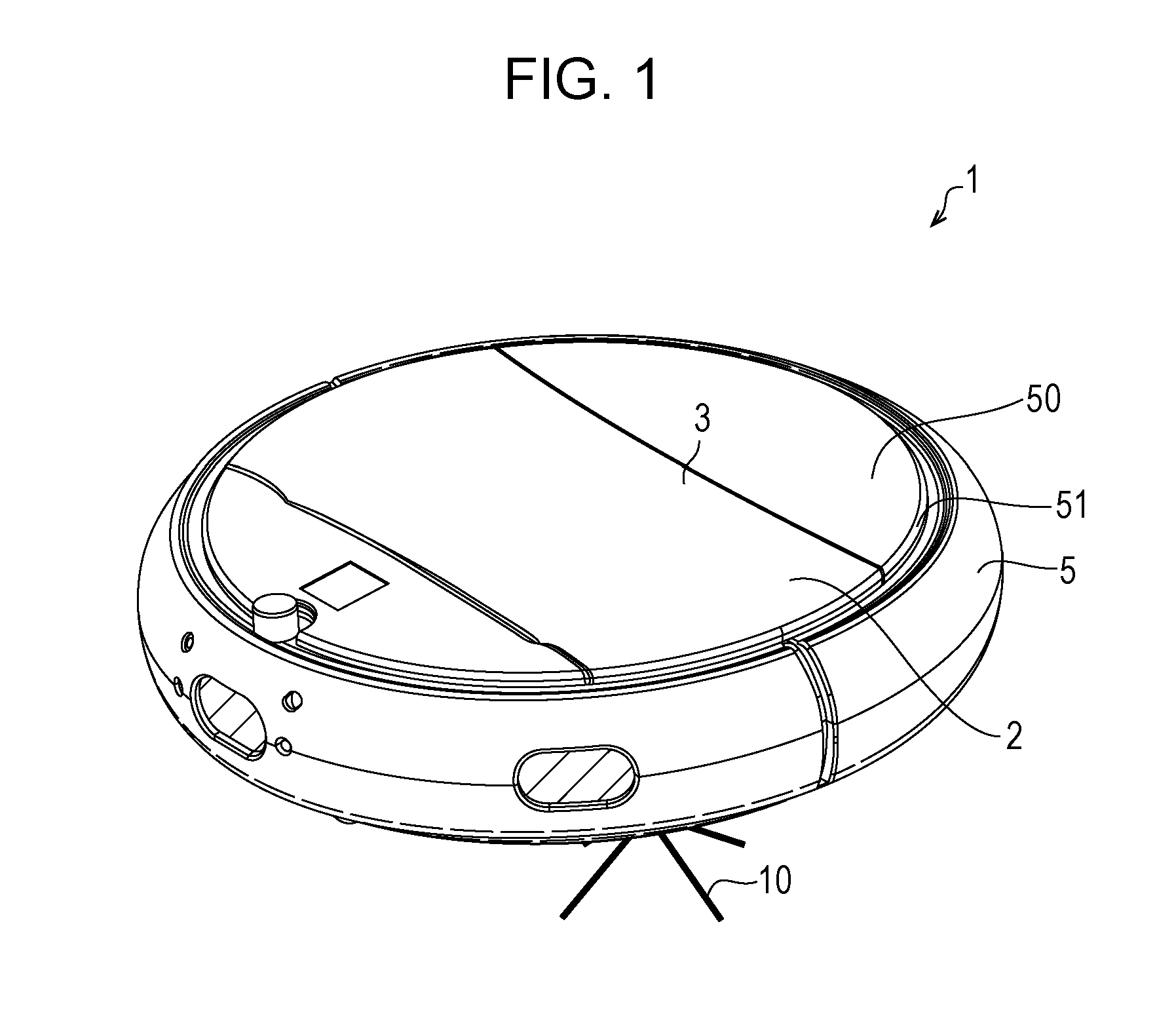
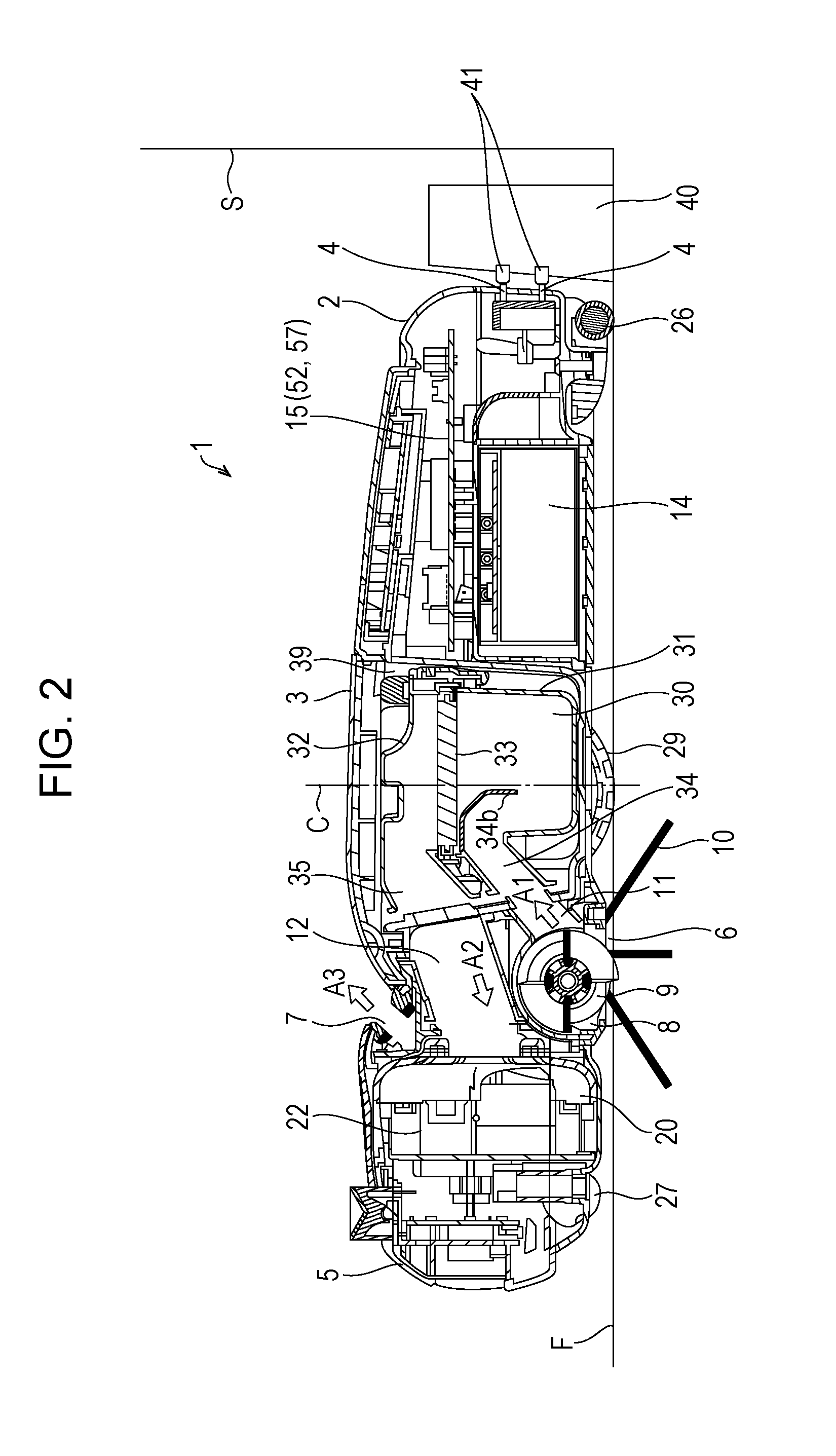
[0024]FIGS. 1 to 3 are perspective view, side sectional view, and bottom view, respectively, showing a self-propelled cleaner 1 according to the present embodiment.
[0025]The self-propelled cleaner (self-propelled electronic device) 1, which collects dust (that is, performs cleaning) during self-propelled operation, includes the main body of the self-propelled cleaner 1, which is formed of a main body cabinet 2 having an outer frame of a circular shape in plan view as shown in FIG. 1, and driven wheels 29, which are driven by a battery (secondary battery) 14 as a power supplying source as shown in FIGS. 2 and 3.
[0026]As shown in FIG. 1, an operation panel 50, which inputs an instruction for the self-propelled cleaner 1, a light emitting diode (LED) lamp 51, and a lid 3, which is closed or opened to output or input a dust collector 30, are disposed on an upper surface of the main body cabinet 2. Although the upper surface and lower surface of the main body cabinet 2 are circular in th...
embodiment 2
[0094]Application of the self-propelled electronic device according to the present invention to a self-propelled air cleaner will be described with reference to the drawings.
[0095]Basically, a self-propelled air cleaner (electronic apparatus) 110 according the present embodiment does not have the cleaning function included in the self-propelled cleaner 1 according to embodiment 1, and has an air cleaning function. Accordingly, the components having the same functions as the components described in embodiment 1 are given the same numerals and their descriptions are omitted.
(Structure of a Self-Propelled Air Cleaner)
[0096]FIGS. 11 and 12 are side a sectional view and a perspective view of the self-propelled air cleaner 110 according to the present embodiment, respectively.
[0097]The self-propelled air cleaner 110, which cleans air while being self-propelled, includes the main body of the self-propelled air cleaner 110, which is formed of a main body cabinet 200 having an outer frame of...
embodiment 3
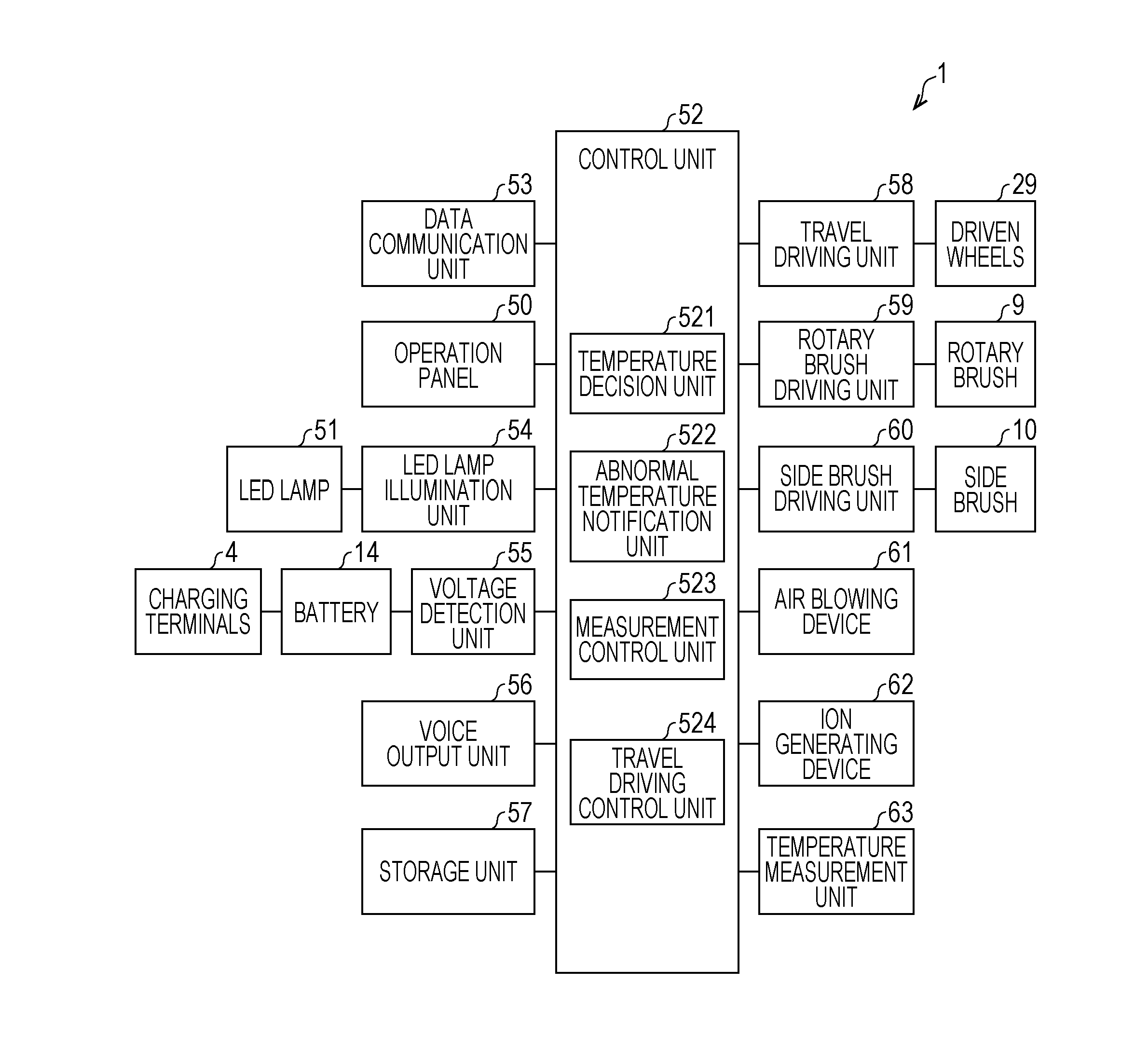
[0114]The control unit 52 of the self-propelled cleaner 1 and the control unit 520 of the self-propelled air cleaner 110 may be configured by hardware logic or by software using a CPU.
[0115]That is, the self-propelled cleaner 1 or the self-propelled air cleaner 110 includes a central processing unit (CPU), which executes instructions in a program that achieve various functions, a ROM (read only memory), which stores the above program, a RAM (random access memory), in which the above program is expanded, a storage device (recording medium) such as memory, which stores the above program and various types of data, and so on. The object of the present invention can also be achieved by supplying, to the self-propelled cleaner 1 or the self-propelled air cleaner 110, a recording medium that records, in a readable manner, program codes (executable program, intermediate code program, and source program) of the control program of the self-propelled cleaner 1 or the self-propelled air cleaner...
PUM
 Abstract
Description
Claims
Application Information
 - R&D
- Intellectual Property
- Life Sciences
- Materials
- Tech Scout
- Unparalleled Data Quality
- Higher Quality Content
- 60% Fewer Hallucinations
Browse by: Latest US Patents, China's latest patents, Technical Efficacy Thesaurus, Application Domain, Technology Topic, Popular Technical Reports.
© 2025 PatSnap. All rights reserved.Legal|Privacy policy|Modern Slavery Act Transparency Statement|Sitemap|About US| Contact US: help@patsnap.com


