Methods, systems, computer program products, and devices for renewable energy site power limit control

Active Publication Date: 2014-12-25
TMEIC
View PDF3 Cites 8 Cited by
  • Summary
  • Abstract
  • Description
  • Claims
  • Application Information

AI Technical Summary

Benefits of technology

The invention provides methods to minimize the windup of an error term integration in a control system. This is done by either limiting the scale of the error term or by stopping the integration when the number of inverters is zero. Additionally, the error term can be added to a power limit command distribution to provide a numerator for the power limit. These methods help to improve the accuracy and stability of the control system.

Problems solved by technology

However, this scenario tends to underutilize the total available power when it varies from inverter to inverter, and cannot regulate total site output power.
Furthermore, such a system cannot regulate power at a point on the grid separated from the collective inverter outputs by grid impedance, especially when there are disturbances in grid voltage and load.
However, traditional controllers can be improved by an effective means of handling non-ideal plant saturation and control loop delay, which cause many problems.
The plant can appear quite nonlinear in this situation and performance suffers if appropriate anti-windup and saturation-dependent integration techniques are not used; and 2) Degraded controller dynamic response due to significant delay in the communications channels used to implement the control loop.
Loop delay can result in unnecessary integrator windup during reference slewing and general instability.
It can also result in large site power overshoot in the case of a power surge if power limit commands are not distributed to inverters appropriately.
The first problem is that of quickly maximizing utilization of available power when it is unequally distributed among inverters.
The second problem is that of handling significant site control loop delay.
This delay is due to site controller task time and communication latency.
This delay greatly restricts controller bandwidth.
Loop delay causes undesired integrator windup when the power limit reference changes.
Another side effect of loop delay is that instantaneous site power surges cannot be corrected in less time than the loop delay.
Often, the utility imposes restrictions such as acceptable site power overshoot or site power positive slew rate.

Method used


Image

  • Methods, systems, computer program products, and devices for renewable energy site power limit control
  • Methods, systems, computer program products, and devices for renewable energy site power limit control
  • Methods, systems, computer program products, and devices for renewable energy site power limit control

Examples


Embodiment Construction

[0060]Reference will now be made in detail to various exemplary embodiments of the invention. However, the embodiments described in the description and shown in the figures are illustrative only and are not intended to limit the scope of the invention, and changes may be made in the specific embodiments described in this specification and accompanying drawings that a person of ordinary skill in the art will recognize are within the scope and spirit of the invention.

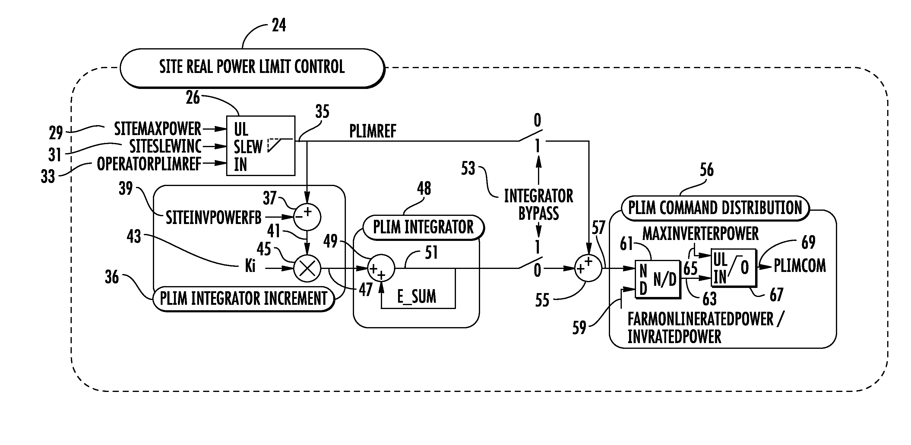
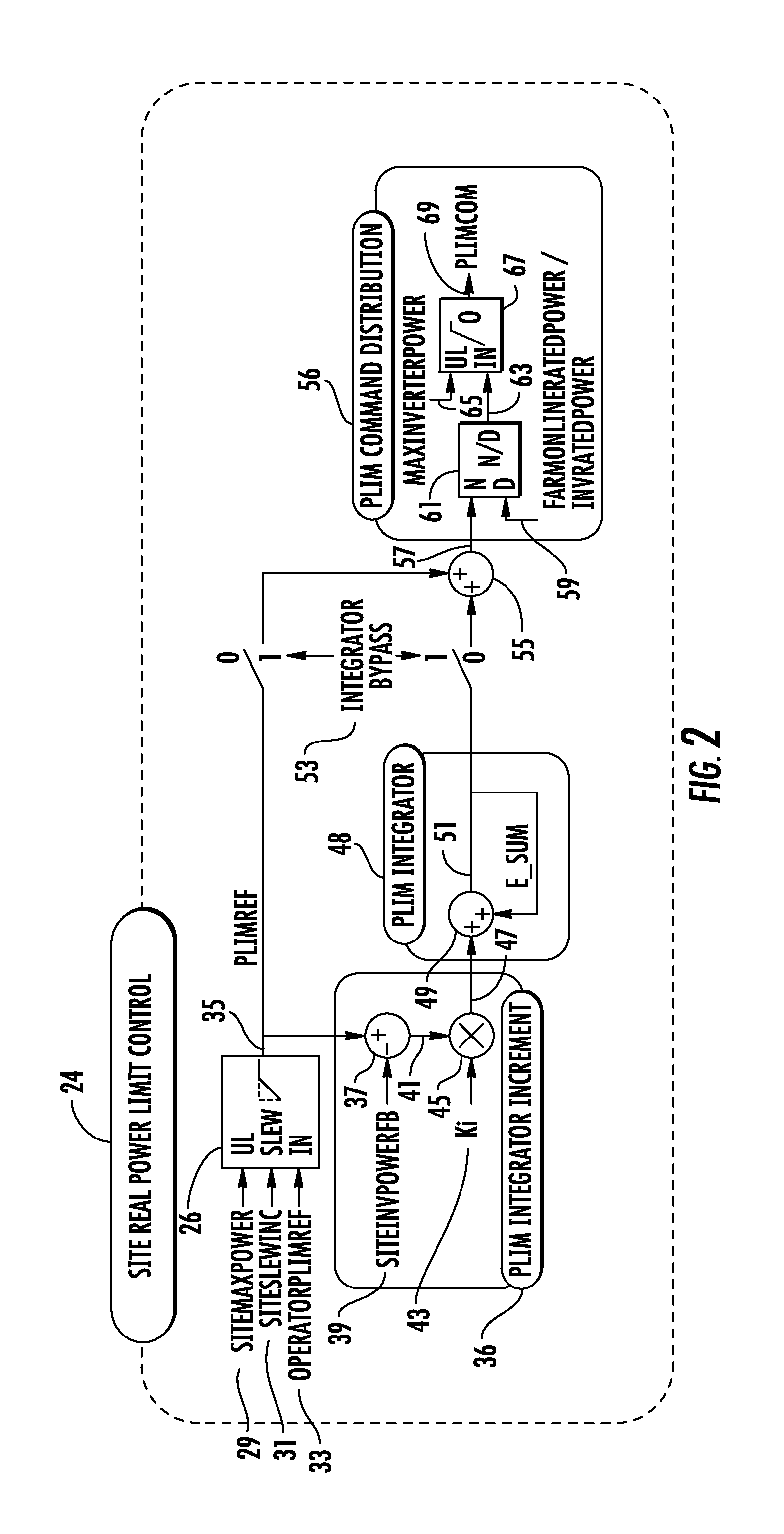
[0061]Conventional power limit controllers produce a single site power limit command, PLimCom, that is distributed equally across inverter controllers. A typical control process is shown in block diagram form in FIG. 2. As shown in FIG. 2, the typical control process 24 calculates 26 a feed-forward power limit reference (PlimRef) 35 based on inputs such as site maximum power (SiteMaxPower) 29, site slew increment (SiteSlewInc) 31, and operator power limit reference (OperatorPlimREf) 33. A power limit (Plim) integrator inc...


PUM


Abstract

The present invention provides methods, systems, computer program products, and devices for renewable energy site power limit control that address conditions of plant saturation and loop delay. In an exemplary embodiment, power limit control of the present invention is broken into two levels of control: a site-wide real power limit control that produces a single site-wide command, SitePlimCom, for all inverters, and inverter-level power limit control that outputs a command, Inv[x].PlimCom[k], for individual inverters. In some embodiments, the invention has one or more of the following features: an integrator with nonlinear gains, limit based anti-windup, a power limit control term based on the sum of both integrator and feed-forward terms, and an inverter-level controller designed to meet slew rate and site power overshoot constraints. The invention can be used at any renewable energy site employing inverters wherein improved dynamic control performance is needed, including solar, wind, and tidal energy sites.

Description

BACKGROUND OF THE INVENTION[0001]1. Field of the Invention[0002]The present invention is related to the control of power limits at renewable energy sites such as solar, wind, and tidal energy sites. More particularly, the present invention relates to renewable energy site power limit control that addresses conditions of plant saturation and loop delay.[0003]2. Description of Related Art[0004]Renewable energy sites are typically composed of multiple power conversion devices connected in parallel generating fixed frequency AC power to a grid. The devices are typically AC-AC or DC-AC inverters. Inverters are designed to extract maximum power from the renewable power supply, subject to a real power limit reference and often, a reactive power command.[0005]A simple and common scenario is to configure inverters individually with the same fixed power limit and reactive power reference and allow them to operate independently to deliver power to the grid. The system is connected in terms of ...

Claims


Application Information

Patent Timeline
IPC IPC(8): H02M1/42
CPCH02M1/42H02M7/493H02J2300/20H02J3/381Y02E10/76H02J3/46
Inventor BIXEL, PAUL S.RUDOLPH, BENJAMIN D.
Owner TMEIC
Why Eureka
Try Eureka