
Systems and methods for increasing efficiency of ultrasound waveform tomography

a synthetic aperture and ultrasound technology, applied in the field of imaging, can solve the problems of increasing the computational cost linearly with the number of transmitting sources, and increasing the computational cost of ultrasound waveform tomography data acquired using a synthetic aperture ultrasound tomography system, so as to reduce the computational time of ultrasound waveform tomography, eliminate unwanted cross interference, and improve the computational efficiency

Active Publication Date: 2014-12-11
TRIAD NAT SECURITY LLC
View PDF3 Cites 6 Cited by
  • Summary
  • Abstract
  • Description
  • Claims
  • Application Information

AI Technical Summary

Benefits of technology

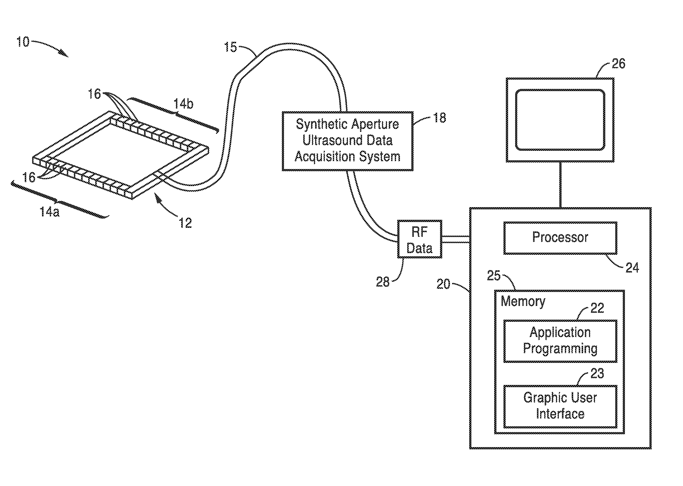
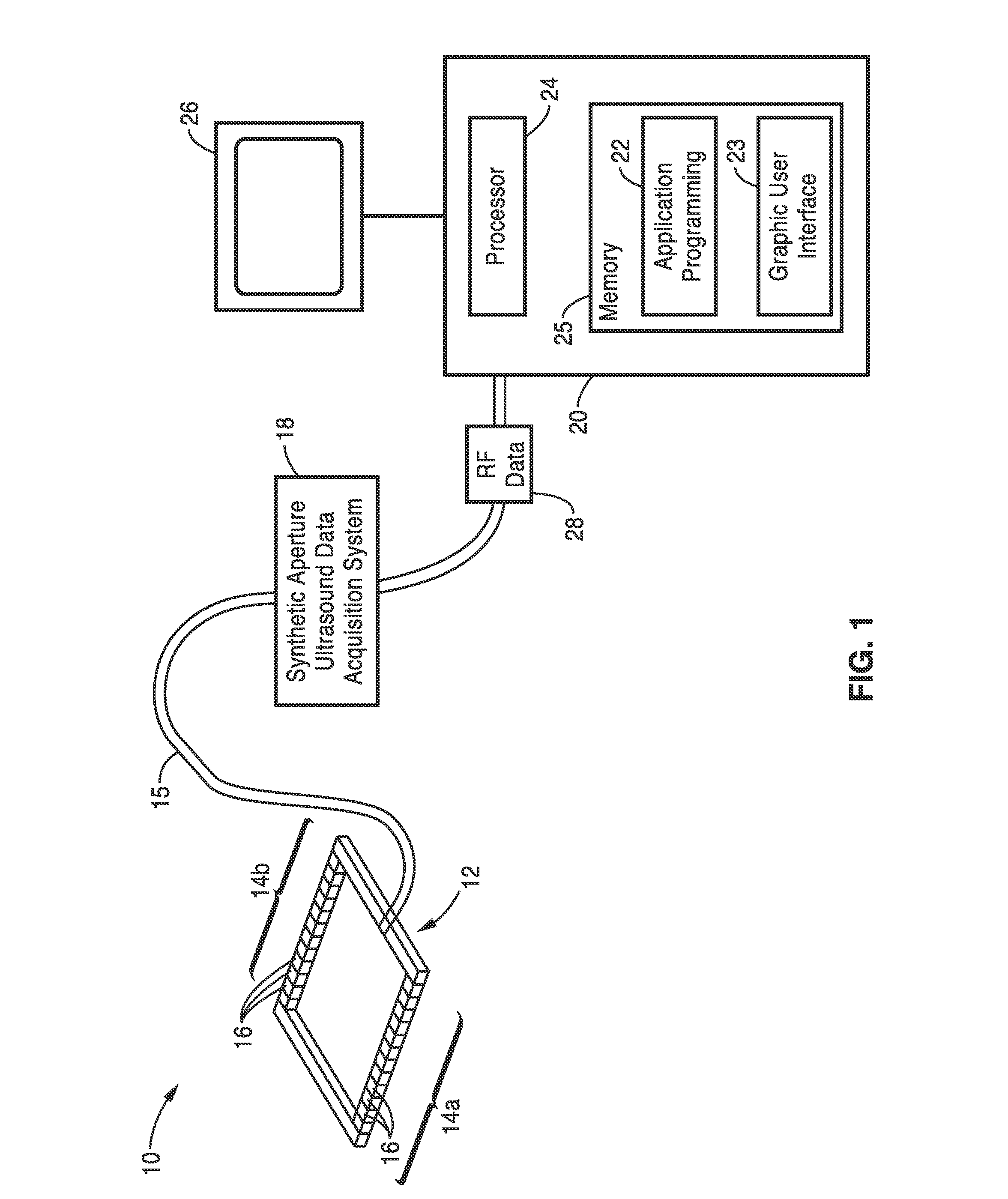
The present invention is a method for improving ultrasound waveform tomography by simultaneously simulating ultrasound waves from multiple transducer elements with random phases to eliminate cross interference. This method significantly reduces the computational time of ultrasound waveform tomography to less than one tenth of that for the original method. The invention also describes a system that uses synthetic-aperture ultrasound to acquire each tomographic slice of patient ultrasound data in real time, allowing for patient data acquisition. The acquired data contains information of ultrasound reflected / scattered and transmitted from all possible directions, resulting in a more accurate, 3-D, high resolution image while minimizing computational costs of the system.

Problems solved by technology

Ultrasound waveform tomography is gaining popularity, but is computationally expensive, even for today's fastest computers.
The computational cost increases linearly with the number of transmitting sources.
However, ultrasound waveform tomography is computationally expensive for data acquired using a synthetic-aperture ultrasound tomography system, particularly for three-dimensional imaging.
In a synthetic-aperture ultrasound tomography system, hundreds to thousands of transducer elements emit ultrasound, which requires an enormous amount of computational time and resources for ultrasound waveform tomography
The main disadvantage of ultrasound waveform tomography is too computationally expensive to be feasible for clinical applications, particularly for large datasets acquired using a synthetic-aperture ultrasound tomography system that consists of hundreds to thousands of transducer elements.

Method used


Image

  • Systems and methods for increasing efficiency of ultrasound waveform tomography
  • Systems and methods for increasing efficiency of ultrasound waveform tomography
  • Systems and methods for increasing efficiency of ultrasound waveform tomography

Examples


Embodiment Construction

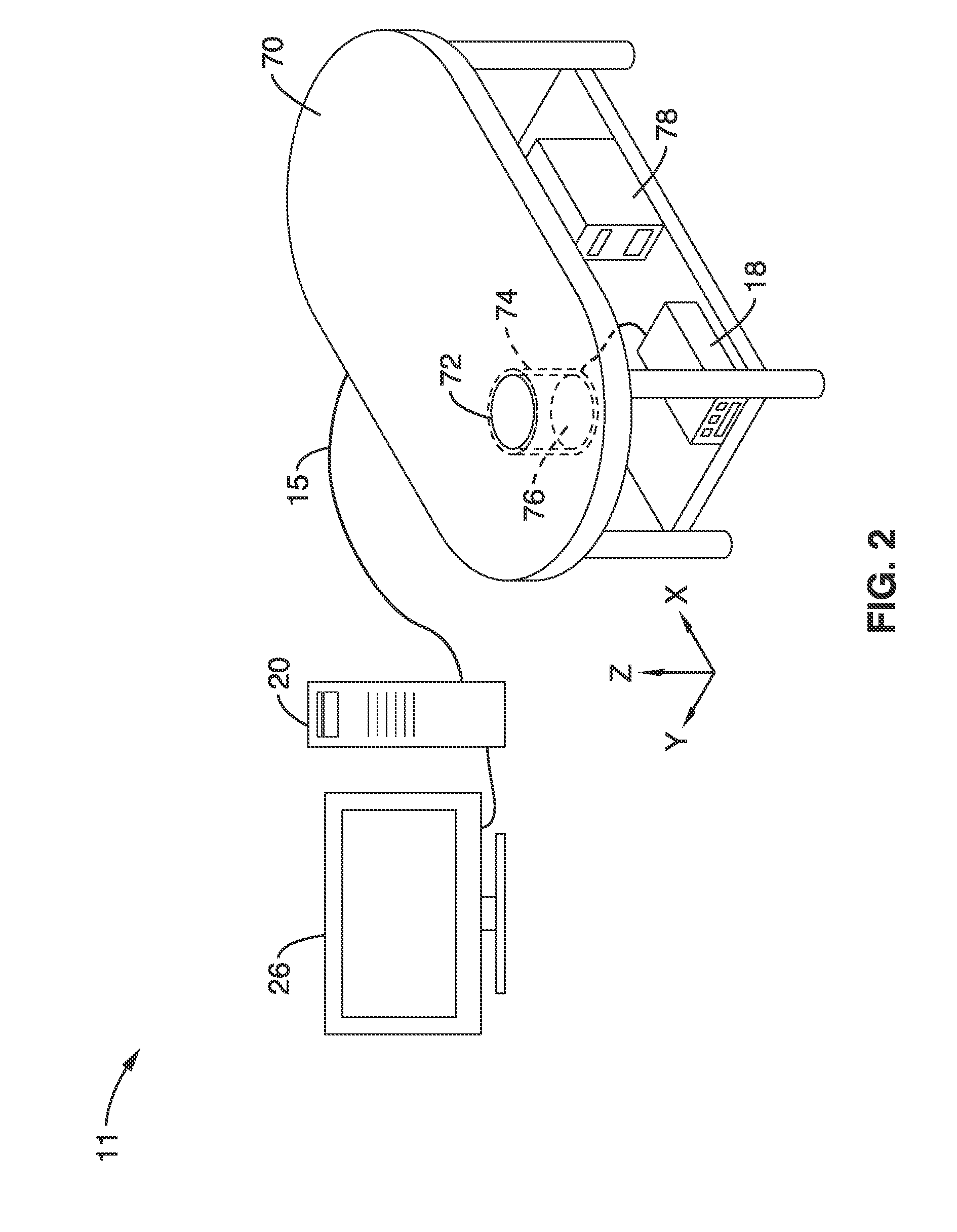
[0053]The description below is directed to synthetic aperture ultrasound tomography systems for imaging a medium such as patient tissue, along with ultrasound waveform tomography methods for acquiring and processing data acquired from these systems, or other systems that may or may not be available in the art.

[0054]The synthetic-aperture breast ultrasound tomography system of the present invention uses synthetic-aperture ultrasound to obtain quantitative values of mechanical properties of breast tissues. In this system, each transducer element transmits ultrasound waves sequentially, and when an ultrasound transducer element transmits ultrasound waves propagating through the breast, all ultrasound transducer elements (at least within a portion of an array) simultaneously receive ultrasound reflection / transmission, or forward and backward scattering signals. The ultrasound reflection / transmission signals are used to obtain quantitative values of mechanical properties of tissue featur...


PUM


Abstract

Ultrasound tomography imaging methods for imaging a tissue medium with one or more ultrasound transducer arrays comprising a plurality of transducers, wherein said transducers comprise source transducers, receiving transducers. The methods include assigning a phase value or time delay to source transducers, exciting the transducers and calculating a search direction based on data relating to the excited transducers.

Description

CROSS-REFERENCE TO RELATED APPLICATIONS[0001]This application is a 35 U.S.C. §111(a) continuation of PCT international application number PCT / US2013 / 024676 filed on Feb. 4, 2013, incorporated herein by reference in its entirety, which claims priority to, and the benefit of, U.S. provisional patent application Ser. No. 61 / 594,865, filed on Feb. 3, 2012, incorporated herein by reference in its entirety. Priority is claimed to each of the foregoing applications.[0002]The above-referenced PCT international application was published as PCT International Publication No. WO 2013 / 116866 on Aug. 8, 2013, incorporated herein by reference in its entirety.STATEMENT REGARDING FEDERALLY SPONSORED RESEARCH OR DEVELOPMENT[0003]This invention was made with Government support under Grant No. MIPROLDATM0144 from the Breast Cancer Research Program of DoD-Congressionally Directed Medical Research Programs and Contract No. DE-AC52-06NA25396 awarded by the Department of Energy. The Government has certain ...

Claims


Application Information

Patent Timeline
IPC IPC(8): A61B8/13A61B5/00A61B8/08
CPCA61B8/13A61B5/7275A61B5/0073A61B8/5207A61B8/4494A61B8/14A61B8/15A61B8/406G01S15/8997G01S15/8929A61B8/0825G06T5/00A61B8/4488A61B8/483A61B8/085A61B8/145A61B8/4477G01S15/8915G06T11/005
Inventor HUANG, LIANJIEZHANG, ZHIGANG
Owner TRIAD NAT SECURITY LLC
Learn More