Edge protection insert mounts for grinding rolls

Inactive Publication Date: 2014-12-11
FLSMIDTH AS
View PDF3 Cites 12 Cited by
  • Summary
  • Abstract
  • Description
  • Claims
  • Application Information

AI Technical Summary

Benefits of technology

This patent aims to provide edge wear components that have better stability and can resist being pulled off. Additionally, it aims to provide a way to quickly repair damaged female threads without having to rework a roller or sleeve portion.

Problems solved by technology

Such methods are time-consuming, inefficient, and costly.
However, these designs are susceptible to “washout”, where roller sleeve substrate material begins to erode due to the migration of abrasive particles forming the autogenous layer.

Method used


Image

  • Edge protection insert mounts for grinding rolls
  • Edge protection insert mounts for grinding rolls
  • Edge protection insert mounts for grinding rolls

Examples


Embodiment Construction

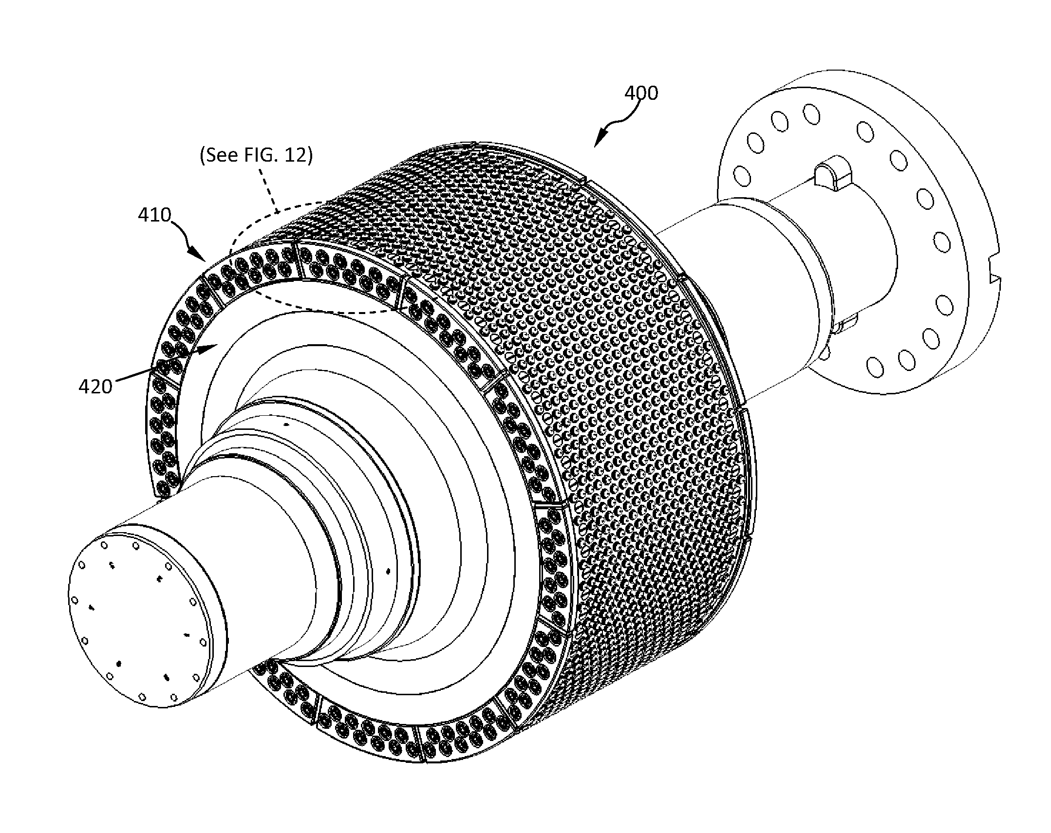
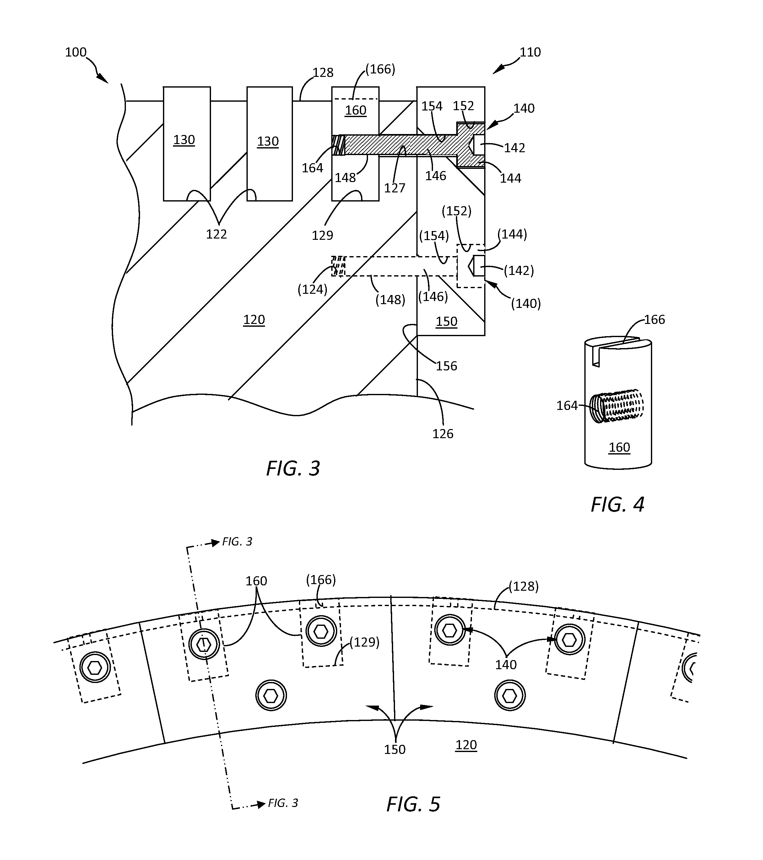
[0030]FIGS. 3-5 show a roller 100 according to some embodiments. The roller 100 may comprise a roller sleeve 120 having a roller end 126 and a roller edge 110. An edge wear component 150 may be threadably secured to the edge 110 of the roller sleeve 120. Wear inserts 130 may be distributed over a cylindrical outer surface 128 of the roller sleeve 120 and may be disposed within wear insert pockets 122. A fastener 140 having a head 144, a drive socket 142, and a shaft 146 comprising male threads 148 may be inserted through the edge wear component 150 until the male threads 148 engage female threads 164 provided within a cylindrically-shaped mounting insert 160. The mounting insert 160 may be disposed within a mounting insert pocket 129, and may be provided with an alignment device 166 such as directional indicia or means for rotating the mounting insert 160, in order to align and facilitate threaded engagement between male threads 148 of the fastener 140 and female threads 164 within ...


PUM

PropertyMeasurementUnit
Currentaaaaaaaaaa
Currentaaaaaaaaaa
Currentaaaaaaaaaa

Abstract

A roller press comprises a roller [100] having: a roller edge [110] formed by the intersection of a roller end [126] and an outer surface [128], an edge wear component [150] provided at said roller edge [110], and a mounting insert [160] provided within a mounting insert pocket [129] located inland of said roller end [126] and spaced from said roller edge [110]. A fastener [140] extends between the edge wear component [150] and the mounting insert [160] to keep the edge wear component [150] attached to the roller [100]. The fastener [140] threadedly engages female threads [164] provided within the mounting insert [160]. Also disclosed, is an edge protection system and method of mounting an edge wear component [150] to a roller [100] in a roller press.

Description

CROSS-REFERENCE OF RELATED APPLICATIONS[0001]This application is an international application which claims the benefit of U.S. Provisional Patent Application No. 61 / 580,342, filed on 27 Dec. 2011.BACKGROUND OF THE INVENTION[0002]This invention relates to crushing, grinding, and comminution equipment, and more particularly to high pressure grinding roller (HPGR) press systems used, for instance, in the mining, cement, coal, and minerals processing industries.[0003]FIG. 1 shows a conventional edge wear component 950 which is threadedly secured to the edge 910 of a roller sleeve 920 which forms a portion of a roller 900. A series of wear inserts 930 are distributed over an outer surface 928 of the roller sleeve 920 and are disposed within wear insert pockets 922. A fastener 940 having a head 944, a socket 942, and a shaft 946 comprising male threads 948 is inserted into a hole within roller sleeve 920, the hole comprising female threads 924. The head 944 of the fastener fits within a h...

Claims


Application Information

Patent Timeline
IPC IPC(8): B02C4/30
CPCB02C4/30B02C4/305Y10T29/49547
Inventor EUCULANO, JASONSCHANTZ, DWAYNE R.
Owner FLSMIDTH AS
Why Eureka
Try Eureka