
Battery charging device for an electric vehicle

a charging device and electric vehicle technology, applied in the direction of electric vehicle charging technology, charging stations, transportation and packaging, etc., can solve the problems of unsuitable applications requiring long lifespans, complicated structure of the electric vehicle charging device b>100/b> described above, etc., and achieve the effect of high power density and long lifespan

Active Publication Date: 2014-11-20
MYONGJI UNIV IND & ACAD COOPERATION FOUND
View PDF2 Cites 8 Cited by
  • Summary
  • Abstract
  • Description
  • Claims
  • Application Information

AI Technical Summary

Benefits of technology

The invention is a battery charging device for electric vehicles that is designed to improve its longevity and suitability for charging high-power batteries. It achieves this by simplifying the structure of the device, removing dead-zones in the input current to improve power factor, and extending the lifespan of the device. This allows for effective charging of electric vehicles and ensures the device is always ready for use.

Problems solved by technology

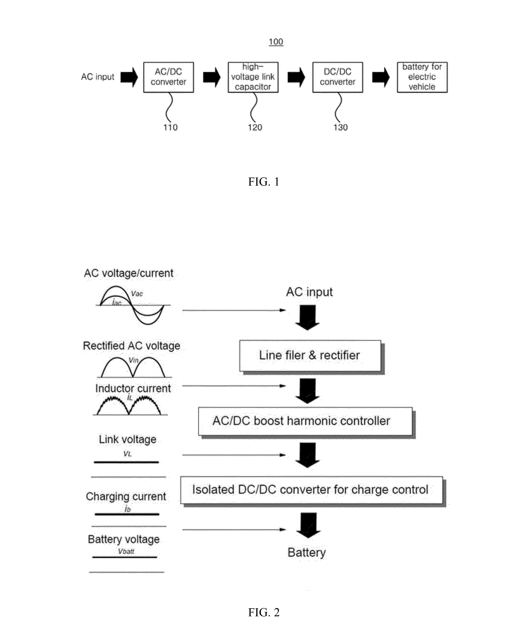
However, the conventional electric vehicle charging device 100 described above has a complicated structure, due to its dual composition.
Also, the conventional electric vehicle charging device 100 may require an electrolytic capacitor having a high capacitance of several thousand uF or higher and a high power density for filtering the fluctuating power, but since the lifespan of an electrolytic capacitor decreases rapidly at high temperatures, it is not suitable for applications requiring long lifespans, such as electric vehicles.

Method used


Image

  • Battery charging device for an electric vehicle
  • Battery charging device for an electric vehicle
  • Battery charging device for an electric vehicle

Examples


Embodiment Construction

[0026]As the present invention allows for various changes and numerous embodiments, particular embodiments will be illustrated in the drawings and described in detail in the written description. However, this is not intended to limit the present invention to particular modes of practice, and it is to be appreciated that all changes, equivalents, and substitutes that do not depart from the spirit and technical scope of the present invention are encompassed in the present invention. In describing the drawings, like reference numerals are used for like components.

[0027]When a component is mentioned to be “coupled” or “connected” to another component, this may mean that it is directly coupled or connected to the other component, but it is to be understood that yet another component may exist in-between. On the other hand, when a component is mentioned to be “directly coupled” or “directly connected” to another component, it is to be understood that there are no other components in-betwe...


PUM


Abstract

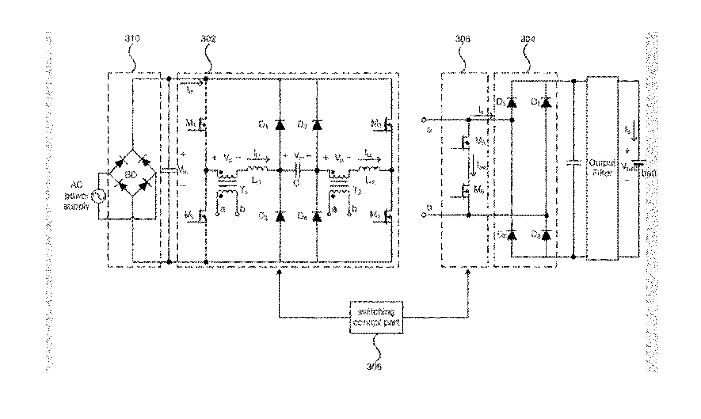
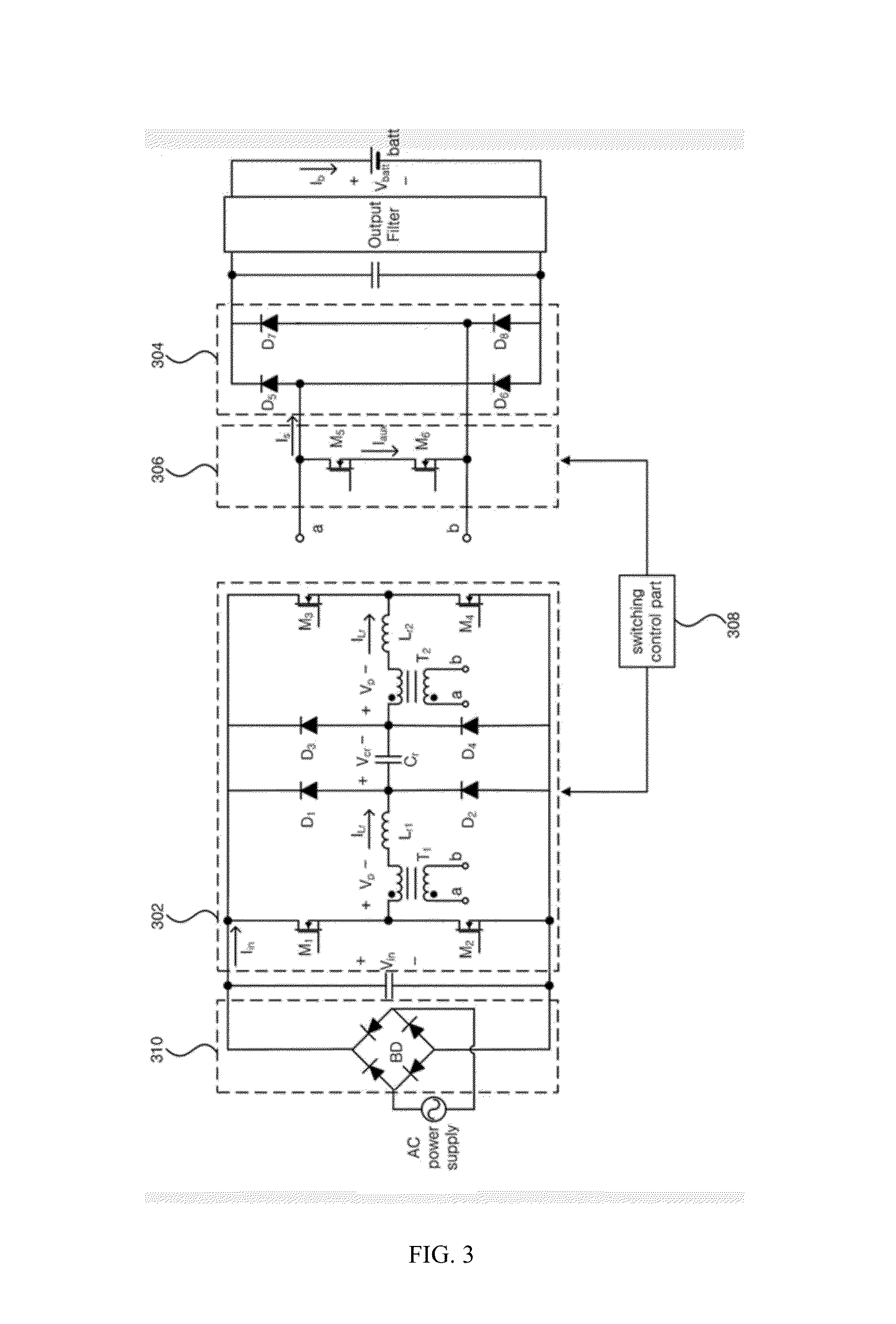
An electric vehicle battery charging device includes: a series resonance part, which receives a rectified voltage, and which includes a transformer, a resonant inductor, and a resonant capacitor; a rectifying part, of which a first input end is connected with one end of a secondary winding of the transformer, a second input end is connected with the other end of the secondary winding of the transformer, and an output end is connected with an electric vehicle battery; and a switching part, of which one end is connected with one end of the secondary winding of the transformer and the first input end of the rectifying part, and the other end is connected with the other end of the secondary winding of the transformer and the second input end of the rectifying part, where the switching part controls the current from the secondary winding of the transformer to the rectifying part.

Description

CROSS-REFERENCE TO RELATED APPLICATIONS[0001]This application is a National Phase application of PCT International Application No. PCT / KR2012 / 008960, which was filed on Oct. 29, 2012, and which claims priority from Korean Patent Application No. 10-2011-0140727 filed with the Korean Intellectual Property Office on Dec. 23, 2011. The disclosures of the above patent applications are incorporated herein by reference in their entirety.BACKGROUND[0002]1. Technical Field[0003]Embodiments of the present invention relate to a battery charging device for an electric vehicle, more particularly to a charging device that ensures a long lifespan and is suitable for charging an electric vehicle battery having a high power density.[0004]2. Description of the Related Art[0005]A device for charging the battery of an electric vehicle (EV) generally uses commercial power. Thus, the battery charging device for an electric vehicle can be used for 110 Vac or 220 Vac and may require consideration of power ...

Claims


Application Information

Patent Timeline
IPC IPC(8): B60L11/18
CPCB60L11/1811Y02T90/14H02M7/219B60L2270/147B60L2210/00Y02T10/92B60L53/22B60L53/20H02J7/02H02J2207/20B60L53/122Y02T10/7072Y02T10/70Y02T90/12B60L53/53B60Y2200/91
Inventor LEE, JUN-YOUNGYOO, GWANG-MINPARK, SEUNG-HEE
Owner MYONGJI UNIV IND & ACAD COOPERATION FOUND
Learn More