
System and method for feeding a fluid to a mold for molding a reinforced composite structure

a technology of reinforced composite structure and fluid feeding, which is applied in the direction of dough shaping, manufacturing tools, and final product manufacturing, etc., can solve the problems of releasing unhealthy vapors to the environment, affecting the working environment, and difficult to control the propagation of resin in the laminate, so as to reduce the duration of the casting process

Active Publication Date: 2014-11-13
SIEMENS GAMESA RENEWABLE ENERGY AS
View PDF4 Cites 13 Cited by
  • Summary
  • Abstract
  • Description
  • Claims
  • Application Information

AI Technical Summary

Benefits of technology

The invention is about controlling the flow of composite fluid in a wind turbine during the casting process to achieve a desired distribution. This can improve performance and reduce manufacturing time and human interaction required. The technical effect is better performance and lower manufacturing costs.

Problems solved by technology

However, such a buffering container may release unhealthy vapors to the environment or even accidentally be tipped-over.
Accordingly, the buffering container has a negative influence on the working environment.
When using the above described VARTM process, it is difficult to control the propagation of resin in the laminate.
However, the distribution layers do not contribute to the strength of the casted structure after curing.
Further, if the distribution layers are removed from the cured structure, they leave a negative impression on the surface of the structure, such that additional post-treatment is required to re-establish the desired surface form.
A further problem of the VARTM process is that static pressure drops may occur between mold inlets which are arranged at different heights.

Method used


Image

  • System and method for feeding a fluid to a mold for molding a reinforced composite structure
  • System and method for feeding a fluid to a mold for molding a reinforced composite structure
  • System and method for feeding a fluid to a mold for molding a reinforced composite structure

Examples


Embodiment Construction

[0052]The illustrations in the drawings are schematically. It is noted that in different figures, similar or identical elements are provided with the same reference numerals or with reference numerals which only differ from the corresponding reference numerals within the first digit.

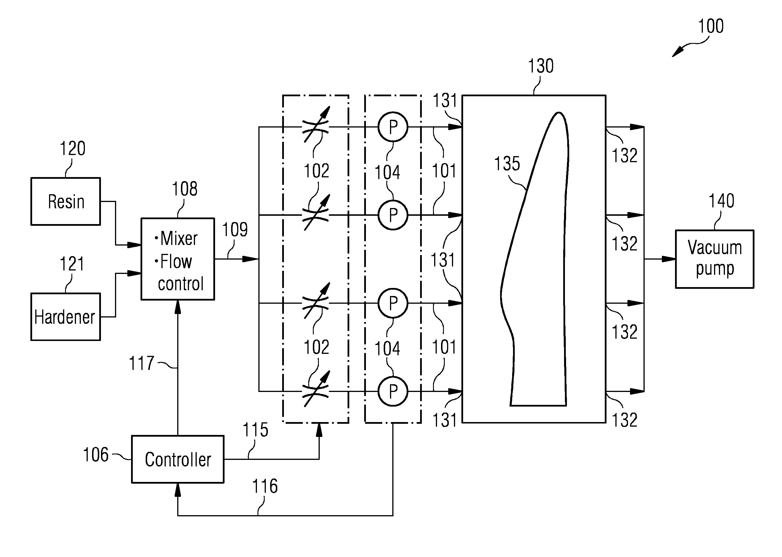
[0053]FIG. 1 shows a system 100 for feeding a composite fluid to a mold 130 in accordance with a first embodiment of the invention. The illustrated mold 130 is designed to cast a composite structure, such as a blade 135 for a wind turbine, by means of a Vacuum Assisted Resin Transfer Molding (VARTM) process. However, it is noted that the system 100 is not limited to be used with this particular kind of mold 130. Further, the mold 130 comprises four mold inlets 131 for receiving composite fluid during a casting process and four mold outlets 132. The mold outlets 132 are connected to a vacuum pump 140.

[0054]The depicted system 100 comprises four feeding units 101. Each feeding unit is shown as being connec...


PUM

PropertyMeasurementUnit
heightaaaaaaaaaa
lengthaaaaaaaaaa
flow rateaaaaaaaaaa

Abstract

A system and method for feeding a composite fluid to a mold for casting a reinforced composite structure, such as a rotor blade for a wind turbine are provided. The system includes a first feeding unit for feeding a first flow of composite fluid to the mold through a first mold inlet, and a second feeding unit for feeding a second flow of composite fluid to the mold through a second mold inlet. The first flow of composite fluid and the second flow of composite fluid are individually controllable.

Description

CROSS REFERENCE TO RELATED APPLICATIONS[0001]This application is the U.S. National Stage of International Application No. PCT / EP2012 / 052270 filed Feb. 10, 2012, and claims the benefit thereof. The International Application claims the benefit of European Application No. EP 11189531 filed Nov. 17, 2011. All of the applications are incorporated by reference herein in their entirety.FIELD OF INVENTION[0002]The present invention relates to the field of casting reinforced composite structures, more particularly to casting of blades for wind turbines.ART BACKGROUND[0003]Reinforced composite structures, such as rotor blades for wind turbines, can be produced by means of a process known as VARTM (Vacuum Assisted Resin Transfer Molding). In such a process, which is e.g. described in WO 2009 / 103736 A2, resin and hardener is mixed in a mixer which in turn supplies the mixed resin to the mold. The flow of the mixed resin to the mold is driven by vacuum in the material to be casted and is, depend...

Claims


Application Information

Patent Timeline
Patent Type & Authority Applications(United States)
IPC IPC(8): B29C70/54B29C70/48
CPCB29C70/546B29C70/48B29L2031/08B29C31/04B29C70/443B29L2031/085Y02P70/50
Inventor HARBOE, NIELSJENSEN, CASPER HOUMANN
Owner SIEMENS GAMESA RENEWABLE ENERGY AS
Learn More