
Method for operating an oxygen blowing lance in a metallurgical vessel and a measurement system for determining a measurement signal used in the method

a technology of oxygen blowing lance and metallurgical vessel, which is applied in the direction of furnaces, furnace monitoring devices, charge manipulation, etc., can solve the problems of nozzle wear, premature separation of the jet from the nozzle wall, and wear of the nozzle edg

Inactive Publication Date: 2014-11-06
SMS GRP GMBH
View PDF3 Cites 13 Cited by
  • Summary
  • Abstract
  • Description
  • Claims
  • Application Information

AI Technical Summary

Benefits of technology

The patent aims to create a solution for continuously detecting the signals of operating parameters during the operation of a gas-blowing lance, especially an oxygen blowing lance, in a metallurgical vessel for the purpose of process control.

Problems solved by technology

As soon as the real flow through the nozzle deviates from the ideal design state or ideal operating point, however, complex flow patterns (diamond wave patterns) in the form of expansion waves or density surges develop both inside and outside the nozzle, which can cause wear of the nozzle edge and lead to premature separation of the jet from the nozzle wall.
When the cold gas jet separates from the nozzle wall, a recirculation region develops, which allows hot converter gas to reach the nozzle wall, as a result of which the nozzle suffers wear.
The exact pressure loss Δpverl is difficult to determine theoretically, because to do this it is necessary to perform a compressible pressure loss calculation for all the components, for which purpose the exact layout of the gas lines must be known.
If it does not, the service life of the lance and the stability of the process will become worse.
As a result of the decarburization reaction, the volume of slag increases enormously, so that slag can actually be ejected, which results in an increase in production costs and the risk of a shutdown.
This skull which forms on a blowing lance is undesirable and must be removed, because the overall mass of the blowing lance increases undesirably and the orifices of the supersonic nozzles can become partially clogged.
The disadvantage of using data loggers is that the pressure loss Δpverl, the inlet pressure p0t present during the course of operation, and the inlet temperature T0t present during the course of operation can be determined only after the fact, i.e., after the lance has been taken out.
The inlet pressure p0t and the inlet temperature T0t are not recorded continuously in real time during the blowing process, which means that it is not guaranteed that the supersonic nozzle of the blowing lance will operate at its ideal operating point during the course of operation.
The disadvantage of this solution is that the vibrations measured on the carriage are much weaker than those which occur at the tip of the lance, which is the area most affected by slag formation, and they can also be influenced by variables which are independent of the process.
In addition, in the case of measurements which are conducted above the lance dome, the deflections of the blowing lance are not detected in optimal fashion.
Finally, in the case of measurement sensors mounted near the blowing lance dome, there is the danger that they can suffer wear and be damaged as a result of the heat to which they are subjected and the effect of the dust acting on them.
This method for determining the time of ignition during the blowing process on the basis of observation, from the outside, of the light emissions from the arcing zone which forms at the time of ignition suffers from the disadvantage that, as a result of the large amount of smoke generated after ignition, information on the ignition process can be obtained only indirectly via the radiation of this smoke.
As a result, the reliability of the measurement result is limited.
In addition, it is impossible to determine in a differentiated manner the ignition of the individual oxygen jets, usually five to six, emerging from a multi-hole nozzle.

Method used


Image

  • Method for operating an oxygen blowing lance in a metallurgical vessel and a measurement system for determining a measurement signal used in the method
  • Method for operating an oxygen blowing lance in a metallurgical vessel and a measurement system for determining a measurement signal used in the method
  • Method for operating an oxygen blowing lance in a metallurgical vessel and a measurement system for determining a measurement signal used in the method

Examples


Embodiment Construction

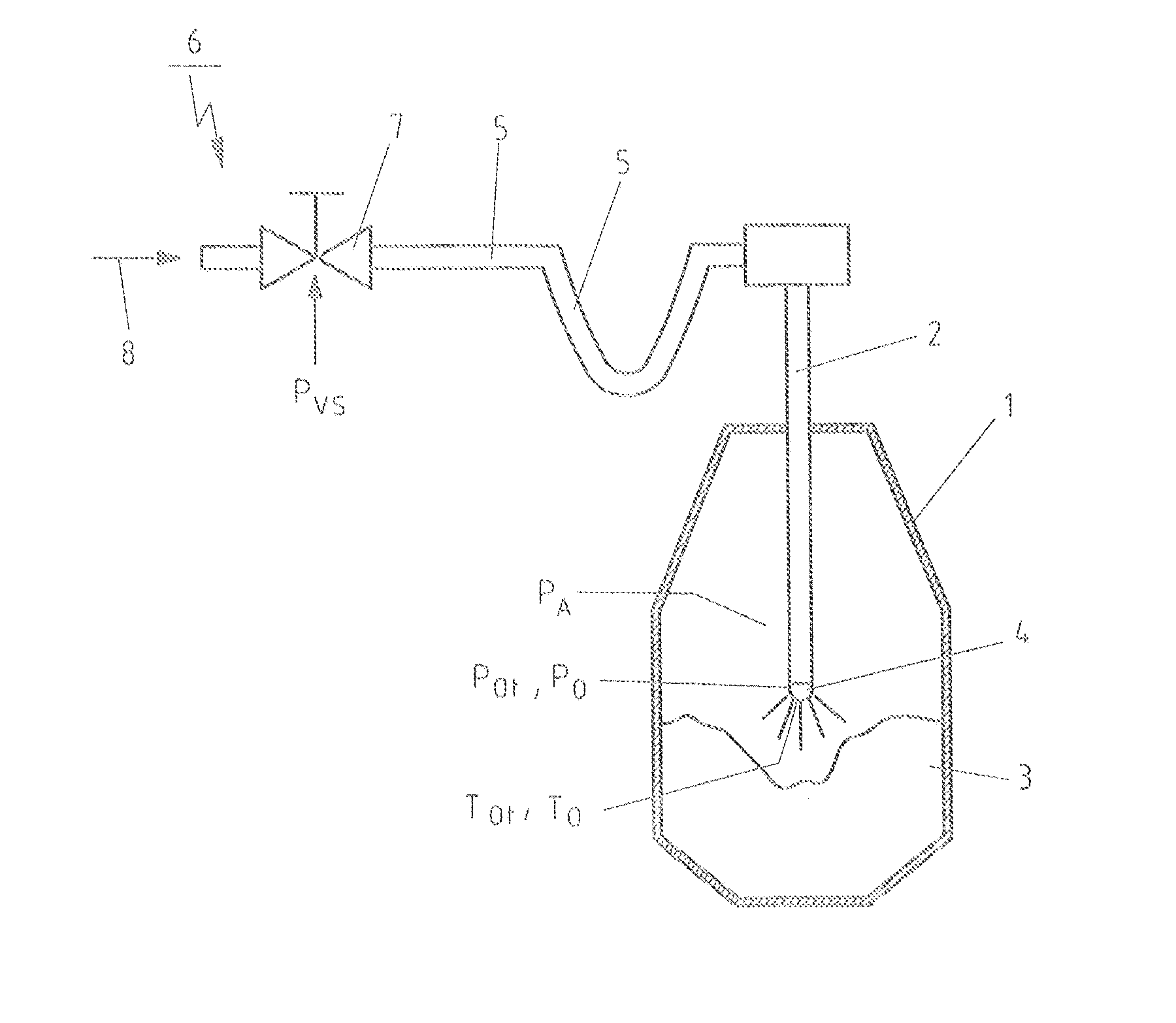
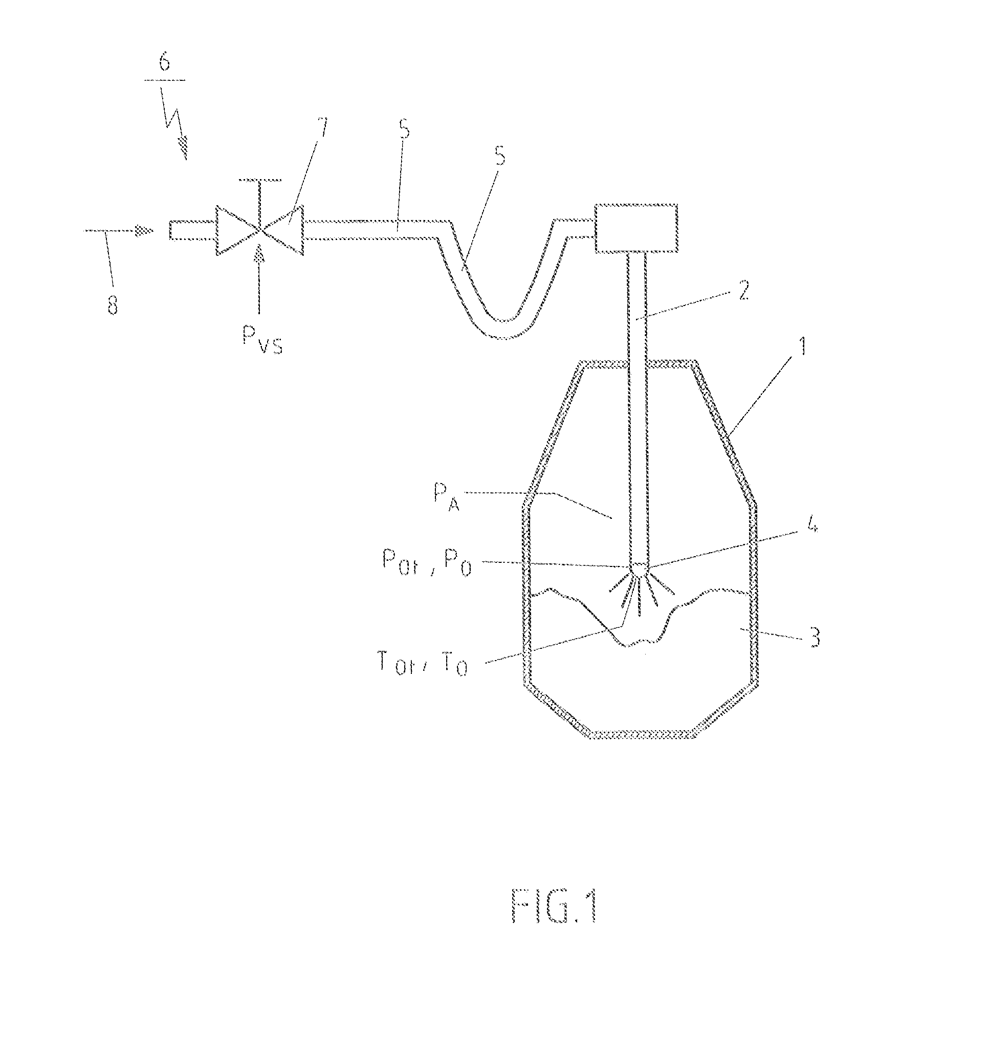
[0049]FIG. 1 shows a blowing lance 2, especially an oxygen blowing lance, which has been introduced from above into a metallurgical vessel 1 designed as a converter; when in operation in the working position shown in FIG. 1, the lance blows gas onto a metal bath 3 in the metallurgical vessel 1. At the end of the blowing lance 2 located at the bottom in the diagram of FIG. 1, a replaceable head 4 is mounted, which forms the tip of the blowing lance. Inside the head 4 of the lance are several supersonic nozzles, which are indicated by the dashes proceeding from the head 4 of the lance.

[0050]Through a feed line 5 consisting of pipes or hoses, the blowing lance 2 is connected to a gas feed station 6, which comprises a valve station 7, by means of which the gas 8 to be blown out from the head 4 of the lance can be supplied in regulated fashion to the feed line 5. In the exemplary embodiment, the gas 8 is a gas used in oxygen blowing processes, that is, oxygen or an oxygen-containing gas ...


PUM

PropertyMeasurementUnit
Temperatureaaaaaaaaaa
Pressureaaaaaaaaaa
Poweraaaaaaaaaa

Abstract

A method for operating a blowing lance for blowing a gas in a metallurgical vessel, wherein the head of the blowing lance includes at least one supersonic nozzle, operating parameter measurement signals used for the purpose of process control are continuously acquired. The inlet pressure and / or the inlet temperature of the gas at the supersonic nozzle and / or the vibration amplitude and / or the vibration frequency of the blowing lance and / or the time at which ignition occurs during the oxygen blowing process and / or the location at which ignition occurs during the oxygen blowing process is detected and / or measured in the head of the lance by a detector or sensor arranged in the head of the lance near the supersonic nozzle during operation of the blowing lance. The measurement signal(s) are transmitted to a control unit connected to the detector or sensor and made available for controlling the operation of the blowing lance.

Description

CROSS-REFERENCE TO RELATED APPLICATIONS[0001]The present application claims priority of DE 10 2013 208 079.4, filed May 2, 2013, the priority of this application is hereby claimed and this application is incorporated herein by reference.BACKGROUND OF THE INVENTION[0002]The invention pertains to a method for operating a gas-blowing lance, especially an oxygen blowing lance, in a metallurgical vessel, wherein the preferably replaceable head of the blowing lance comprises at least one supersonic nozzle. The invention is also directed at a measurement system for determining measurement signals used during the operation of a gas-blowing lance, especially an oxygen blowing lance, in a metallurgical vessel for the purpose of process control, wherein the measurement system includes a blowing lance, preferably an oxygen blowing lance, with a preferably replaceable head comprising at least one supersonic nozzle, and an evaluation and / or process control unit to receive and process the measurem...

Claims


Application Information

Patent Timeline
IPC IPC(8): C21C5/32C21C5/46
CPCC21C5/4606C21C5/32C21C5/4613C21C5/4673F27B3/085F27D3/16F27D19/00F27D21/0014F27D2003/164F27D2003/169F27D2019/0043F27D2021/0007
Inventor GRYGOROV, PAVLOODENTHAL, HANS-JURGENSCHLUTER, JOCHENUEBBER, NORBERT
Owner SMS GRP GMBH
Learn More