
Fiber-Grating Sensors Having Longitudinal-Strain-Inducing Jackets and Sensor Systems and Structures Including Such Sensors

a technology of longitudinal strain and fiber grating, which is applied in the direction of converting sensor output, measuring optical property variation, instruments, etc., can solve the problems of increasing cost, reducing the degree of birefringence induced by small to moderate transverse loads, and conventional sensors, so as to increase the magnitude of compressive load and increase the axial tensile strain

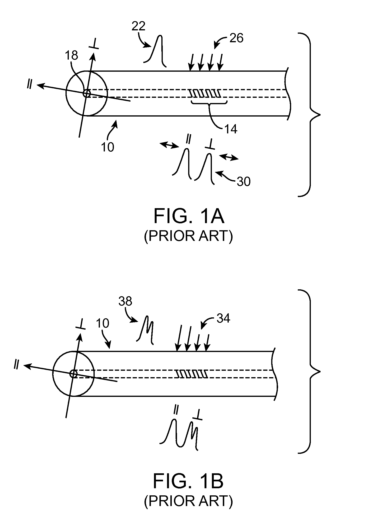
Inactive Publication Date: 2014-10-30
WICOR HOLDING
View PDF6 Cites 20 Cited by
  • Summary
  • Abstract
  • Description
  • Claims
  • Application Information

AI Technical Summary

Benefits of technology

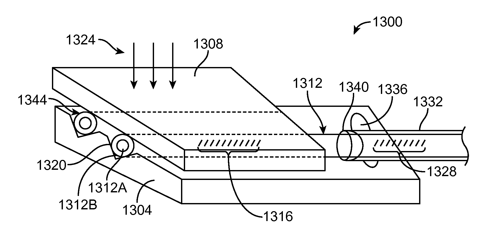
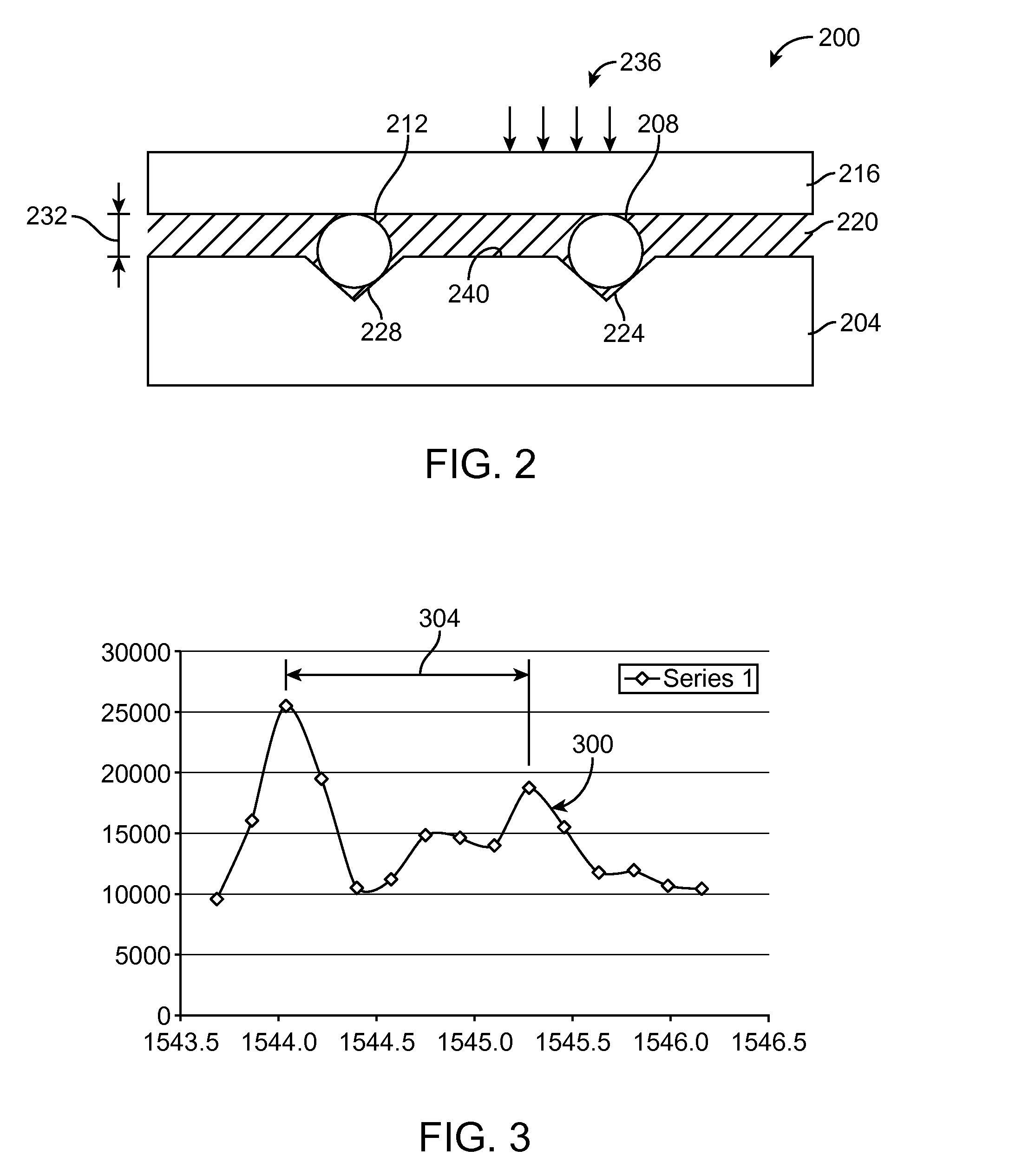
The present patent is about a sensor for measuring a compressive load and an electrical transformer with a clamping load. The sensor includes an optical fiber with a Bragg grating and a longitudinal-strain-inducing jacket that increases strain in the fiber at the Bragg grating as the load increases. The electrical transformer also includes a transverse-pressure sensor that measures the clamping load by inducing axial strain in the fiber at the Bragg grating as the load changes. The sensor and the transformer provide a way to measure the load during use without interfering with the load measurement.

Problems solved by technology

There are a number of significant issues with the conventional sensors that measure transverse load.
One issue is that the amount of birefringence induced by small to moderate transverse loads is very small.
Significant efforts are required to accurately read out these differences and that in turn drives up cost.
This results in larger sensors, increased cost, and in some cases a need for high precision in alignment and fabrication methods.
This requirement makes it more difficult to employ some conventional geometries, including geometries utilizing side-hole optical fibers.

Method used


Image

  • Fiber-Grating Sensors Having Longitudinal-Strain-Inducing Jackets and Sensor Systems and Structures Including Such Sensors
  • Fiber-Grating Sensors Having Longitudinal-Strain-Inducing Jackets and Sensor Systems and Structures Including Such Sensors
  • Fiber-Grating Sensors Having Longitudinal-Strain-Inducing Jackets and Sensor Systems and Structures Including Such Sensors

Examples


Embodiment Construction

[0036]In some aspects, the present invention is directed to an optical-fiber-based sensor that includes an optical fiber, at least one Bragg grating applied to the optical fiber, and one or more longitudinal-strain-inducing (LSI) coatings, or other jacket(s), applied to the optical fiber. Each LSI jacket is selected for measuring a particular physical characteristic by inducing a longitudinal strain into the optical fiber at a corresponding Bragg grating. In the case of transverse load, the jacket elongates causing longitudinal strain through the action of an appropriately designed transducer. Examples of physical characteristics that a sensor of the present disclosure can be designed and configured to measure include, but not limited to, a load applied transverse the optical fiber, temperature, and presence and / or amount of a substance, such as moisture or a particular chemical analyte, and any combination thereof. By virtue of the nature of each LSI-jacket material itself and / or t...


PUM


Abstract

A sensor comprising an optical fiber that includes a Bragg grating and a longitudinal-strain-inducing (LSI) jacket for inducing longitudinal strain into the optical fiber as a function of a transverse load, i.e., pressure or force. As the LSI jacket induces strain into the optical fiber, the fiber grating deforms, thereby changing the character of light reflected from the grating. The changes in character of the reflected light can be measured using suitable optical instrumentation. Additional physical characteristics that can be measured / sensed using an LSI-jacket-based sensor include moisture content / presence, chemical content / presence, and temperature. A transverse-load-sensing sensor can include transverse-load-applying structures that compress the LSI jacket under transverse load, causing the jacket to controllably elongate and thereby induce longitudinal strain into the optical fiber. Chemical and moisture LSI jackets can comprise materials that swell in the presence of the chemical or moisture.

Description

RELATED APPLICATION DATA[0001]This application claims the benefit of priority of U.S. Provisional Patent Application Ser. No. 61 / 816,466, filed on Apr. 26, 2013, and titled “TRANSVERSE FORCE SENSOR WITH TEMPERATURE COMPENSATION,” which is incorporated by reference herein in its entirety.FIELD OF THE INVENTION[0002]The present invention generally relates to the field of fiber-grating sensors. In particular, the present invention is directed to fiber-grating sensors having longitudinal-strain-inducing jackets and sensor systems and structures including such sensors.BACKGROUND[0003]Fiber gratings are well known and have been used for measuring axial and transverse loads. Applications of these fiber gratings have been used primarily to measure strain fields in composite materials and in adhesive joints. To measure transverse loads, some conventional sensors rely on embodiments that apply transverse load on an optical fiber. The transverse load induces differential strain across the opti...

Claims


Application Information

Patent Timeline
IPC IPC(8): G01L1/24
CPCG01L1/246G01D5/35316G02B6/022G01L1/243G02B2006/12135
Inventor UDD, ERIC
Owner WICOR HOLDING
Learn More