Vehicle behavior control apparatus

a technology of vehicle behavior and control apparatus, which is applied in the direction of braking systems, instruments, analogue processes for specific applications, etc., can solve the problems that the control cannot achieve the desired behavior of the vehicle body, and the vehicle body may exhibit unintended pitch behavior, etc., to increase the damping force, and reduce the damping force

Active Publication Date: 2014-10-16
TOYOTA JIDOSHA KK
View PDF0 Cites 11 Cited by
  • Summary
  • Abstract
  • Description
  • Claims
  • Application Information

AI Technical Summary

Benefits of technology

The patent describes a control system for vehicles that can independently control the behavior of the vehicle body, such as pitch and heave, by adjusting the damping force of the shock absorbers in the suspension mechanisms. This system can also prevent unintended behaviors and enhance the intended behavior of the vehicle body. The control means can change the damping force of the shock absorber to increase or decrease the vertical force transmitted to the vehicle body, and can adjust the damping force to reduce or increase the vertical displacement of the vehicle body. This system can effectively control the vehicle body and improve its performance.

Problems solved by technology

Thus, when the same magnitude of the driving force or the braking force, for example, is generated on each of the front wheel side and the rear wheel side in order not to allow the travelling vehicle to generate unnecessary acceleration in forward and backward direction of the vehicle, there is a possibility that intended behavior of the vehicle body cannot be achieved by the control because the magnitude of the vertical force acting on the vehicle body differs due to the difference in the characteristics of the suspension mechanism described above.
Specifically, for example, when the vertical force is exerted on the vehicle body in order to suppress the bouncing behavior (heave behavior), unintended pitch behavior may occur on the vehicle body because the magnitude of the acting vertical force differs (becomes uneven) between the front wheel side and the rear wheel side.

Method used


Image

  • Vehicle behavior control apparatus
  • Vehicle behavior control apparatus
  • Vehicle behavior control apparatus

Examples


Embodiment Construction

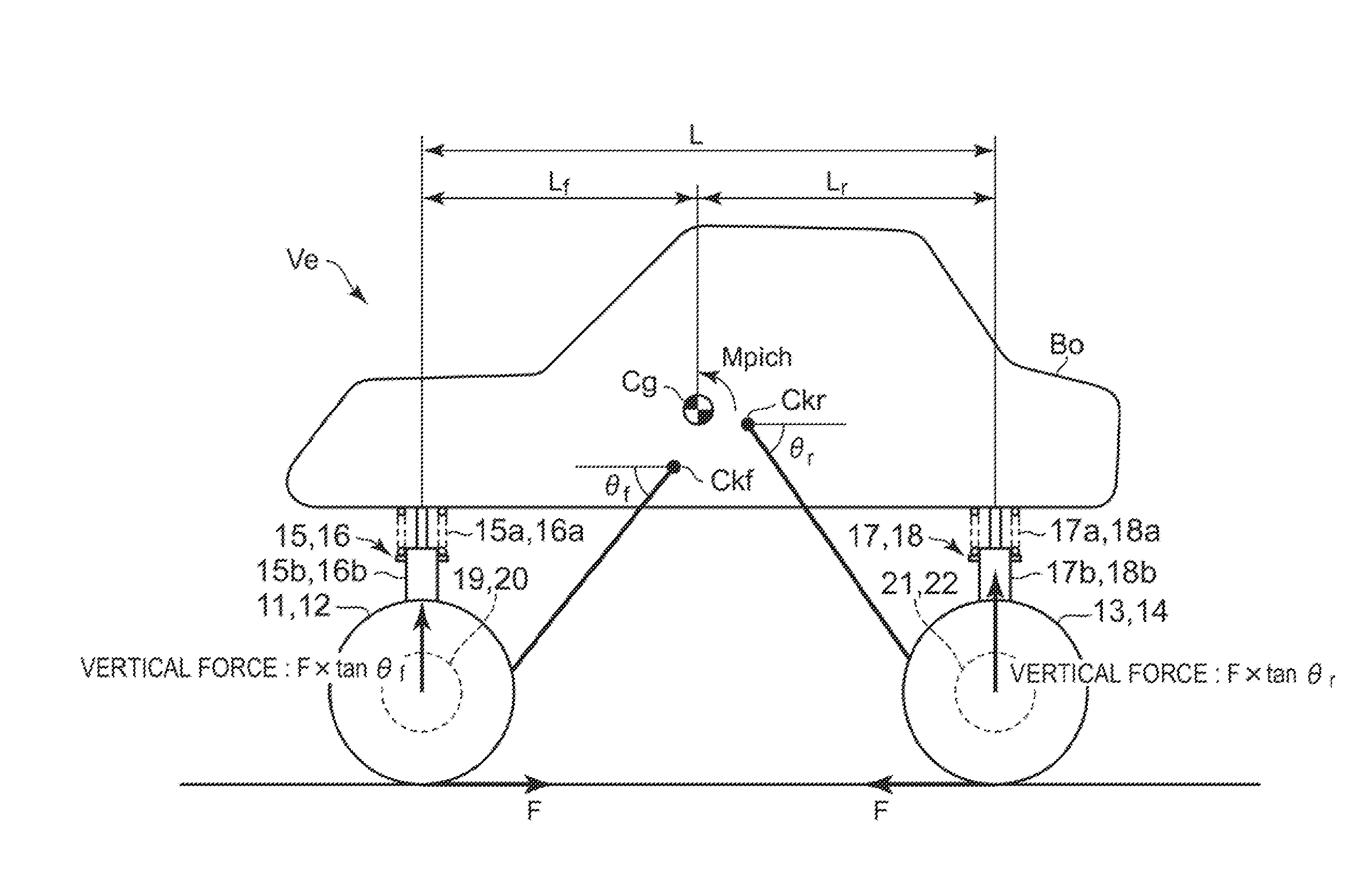
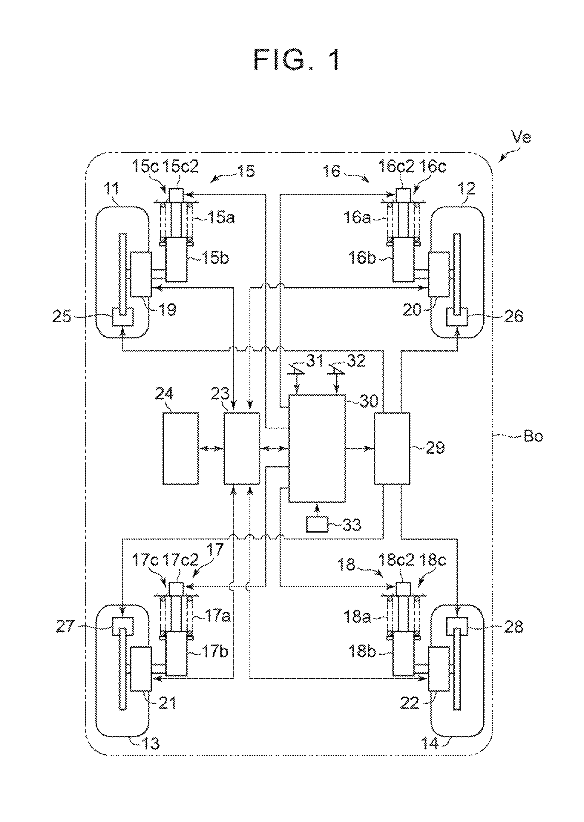
[0031]A detailed description will hereinafter be made on embodiments of the present invention with reference to the accompanying drawings. FIG. 1 schematically shows the structure of a vehicle Ve that is equipped with the vehicle behavior control apparatus according to the present embodiment.

[0032]The vehicle Ve includes right and left front wheels 11, 12 and right and left rear wheels 13, 14 that constitute unsprung members. Each of the right and left front wheels 11, 12 is independently supported by a vehicle body Bo that constitutes sprung members of the vehicle Ve via suspension mechanisms 15, 16. Additionally, each of the right and left rear wheels 13, 14 is independently supported by the vehicle body Bo of the vehicle Ve via the suspension mechanisms 17, 18.

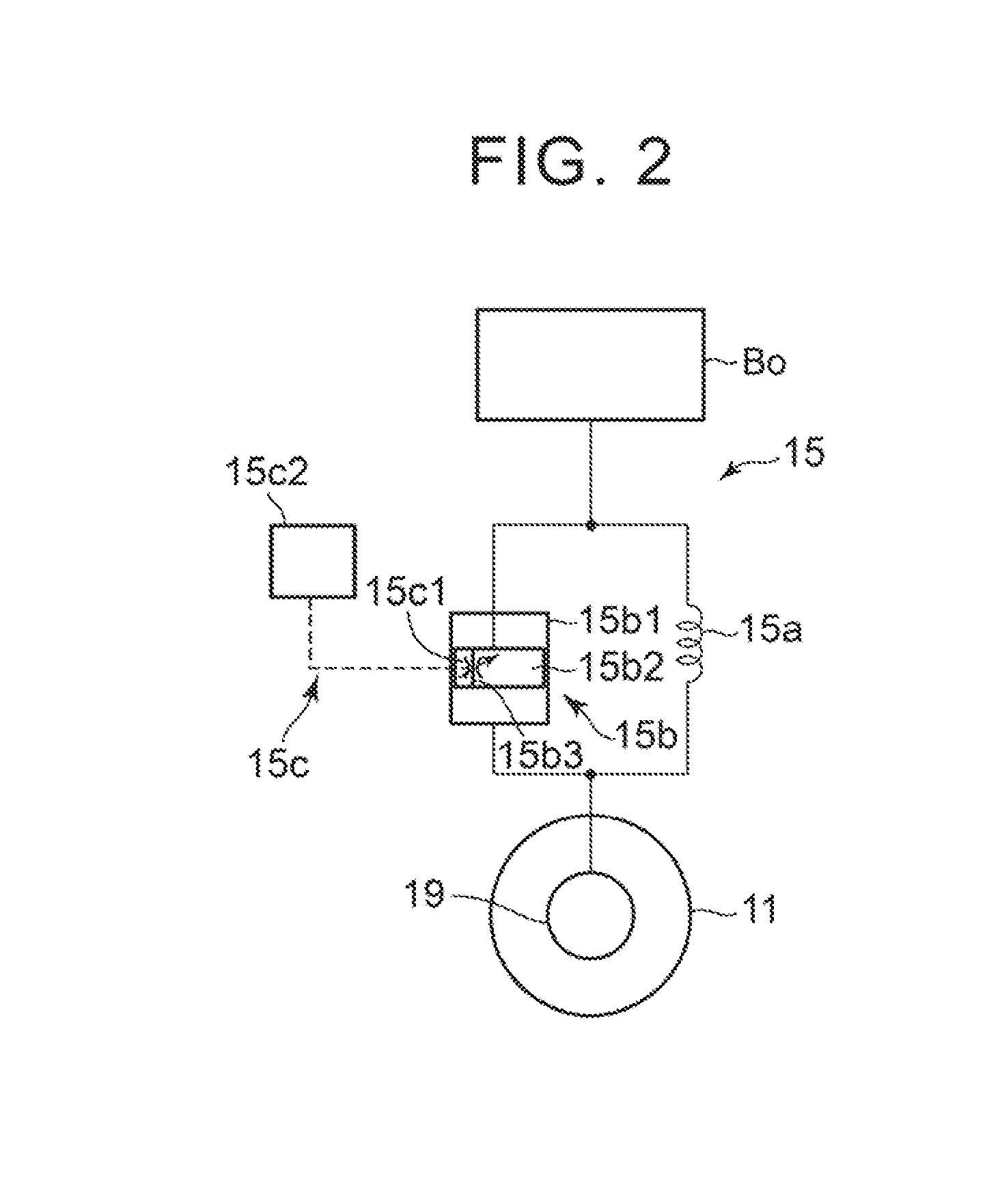
[0033]The suspension mechanisms 15 to 18 include, as shown in FIG. 1, suspension springs 15a to 18a, shock absorbers 15b to 18b, and variable restriction mechanisms 15c to 18c. Here, well-known structures (such as a strut t...


PUM


Abstract

An electronic control unit determines driving force that is generated on wheels and has an identical absolute value and opposite directions to each other in order to suppress pitch behavior and / or heave behavior occurring on a vehicle body in association with travelling of a vehicle. Then, the unit controls the drive of in-wheel motors through an inverter based on the driving force. On the other hand, electronic control unit changes the damping forces of shock absorbers constituting suspension mechanisms in response to the pitch behavior and / or the heave behavior occurring on the vehicle body. In this way, by controlling one of the pitch behavior and the heave behavior that may occur in combination, enhancing of the occurrence of the other one that is not intended can be prevented effectively, and the occurrence of intended behavior on the vehicle body can be controlled independently.

Description

TECHNICAL FIELD[0001]The present invention relates to a vehicle behavior control apparatus that independently controls driving force or braking force generated on wheels of a vehicle in response to behavior occurring on a vehicle body of the vehicle.BACKGROUND ART[0002]Recently, as one form of electric vehicles, a so-called in-wheel motor type vehicle is developed in which a motor is disposed inside a wheel under a spring or in the vicinity of the wheel and the wheel is directly driven by the motor. In the in-wheel motor type vehicle, the motor disposed in each wheel is independently controlled for rotation, that is, the drive (power running) control or regenerative control of each motor is independently performed, and thus the driving force or the braking force provided to each wheel can separately be controlled in response to the travelling state of the vehicle.[0003]With regard to such an in-wheel motor type vehicle, for example, a patent document 1 described below discloses a br...

Claims


Application Information

Patent Timeline
IPC IPC(8): B60T8/1755B60W10/184B60W30/02B60W10/08
CPCB60T8/1755B60W10/08B60W2520/16B60W30/02B60W2030/041B60W10/184B60W10/22B60W30/20B60G2800/164B60G2800/014B60G2500/106B60G2400/102B60G2400/0522B60G2300/50B60T2260/06B60W2710/083B60W2720/16B60K7/0007B60W10/20B60K2007/0038B60K2007/0061B60K17/356B60K2007/0092Y02T10/72
Inventor KATSUYAMA, ETSUO
Owner TOYOTA JIDOSHA KK
Why Eureka
Try Eureka