Preparative column chromatography system

a chromatography system and column technology, applied in the direction of liquid degasification, separation processes, instruments, etc., can solve the problems of inability to fulfil the complete degassing function of the bubble traps installed in the system, adverse effect on the nir measurement upstream of the chromatography column and correspondingly on gradient formation and reproducibility, and inability to transfer process conditions to analytical or semi-preparative systems. to achieve the effect of adjusting the quality of degassing

Active Publication Date: 2014-10-16
F HOFFMANN LA ROCHE & CO AG
View PDF6 Cites 6 Cited by
  • Summary
  • Abstract
  • Description
  • Claims
  • Application Information

AI Technical Summary

Benefits of technology

[0008]Gas escaping from the liquid and also excess liquid can be removed at any time from the bubble trap through the permanent opening at a predefined, adjustable volume flow. Furthermore, the permanent opening improves the degassing of the liquid.
[0061]Furthermore, a very efficient degassing effect is achieved by opening the bubble trap which results from the abrupt pressure drop.

Problems solved by technology

In addition it is almost impossible to transfer the process conditions to analytical or semi-preparative systems.
The application-related high nitrogen and gas contents of the eluents used in chromatographies may result in the liberation of gas dissolved in the eluent during gradient formation which, on the one hand, has an adverse effect on the NIR measurement upstream of the chromatography column and correspondingly also on gradient formation and its reproducibility.
On the other hand, the HPLC columns and in particular the column packing are also affected by this because gas is also liberated within the column packing which can result in the formation of cracks or inhomogeneities within the column packing In conventional HPLC systems the bubble traps which are installed in the systems cannot fulfil a complete degassing function because, like the entire mixing circuit, they are under pressure.

Method used


Image

  • Preparative column chromatography system
  • Preparative column chromatography system
  • Preparative column chromatography system

Examples


example 1

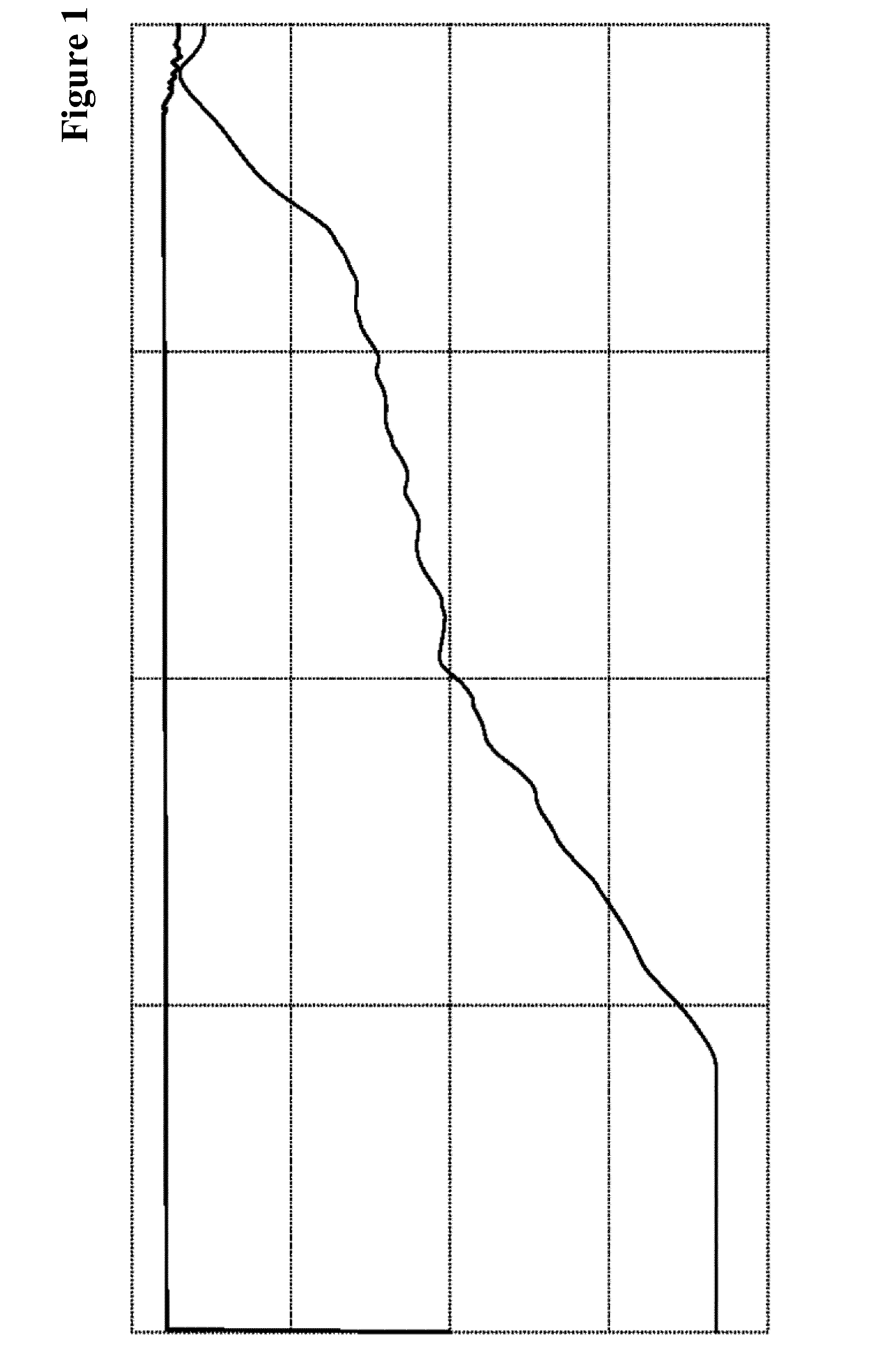
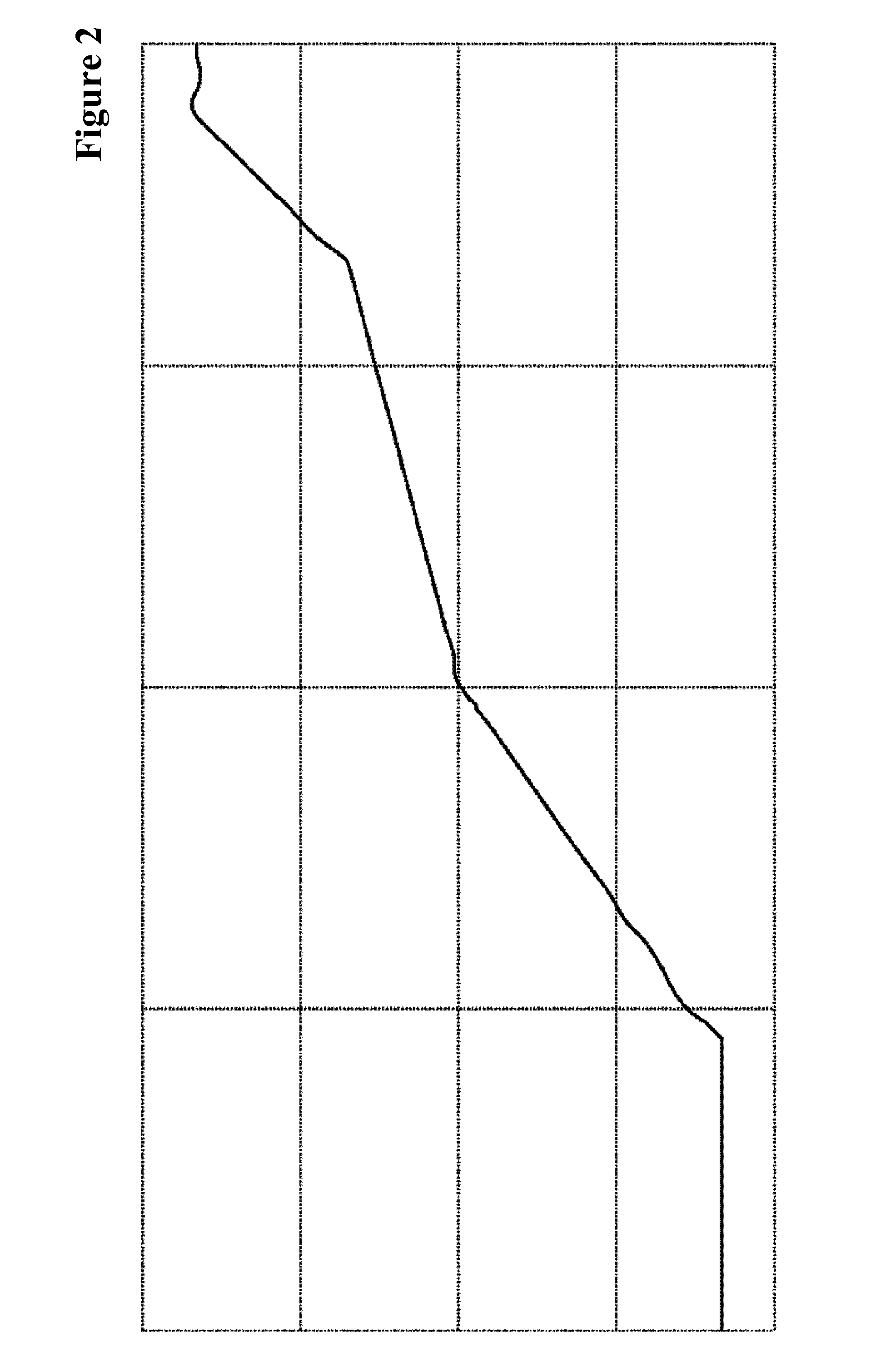
[0095]Differences in the Gradient Time Course in HPLC Systems of Different Designs and Dimensions

[0096]The gradient on an Äkta-HPLC system is exclusively controlled by the defined delivery volumes of the pumps but the actual gradient time course is not taken into consideration. Volume contraction effects are also not taken into consideration.

[0097]The process in a larger production dimension involves adjustment of the buffer composition by means of an NIR detector and consequently the actual buffer composition (gradient) is measured and adjusted.

[0098]The buffer is passed directly downstream of the mixing chamber via the conductivity measuring cell to the NIR detector while bypassing the usual annular valves. It is necessary to increase the flow rate to 60 ml / min because of the large line cross-section in order to have comparable flow conditions. The composition of buffers A and B is the same in both chromatographies.

[0099]The gradient of the previously used separation program was r...

example 2

[0102]Eluent Quantities Discharged by the Bubble Trap Separated from the Mixing Circuit

[0103]Use of an overflowable bubble trap allows excess eluent to be removed from the system in addition to the emitted gases. Since the dimension of the system is in accordance with the maximum column size to be operated, the discharged excess depends on the flow rate that is used and thus on the column diameter that is used.

[0104]When using a column of 30 cm diameter the flow rate is 162 l / h. The overflowable bubble trap is completely filled. Gas and only a small amount of excess eluent must be removed from the system (FIG. 20).

[0105]When using a column of 15 cm diameter the flow rate is 40.5 l / h. The overflowable bubble trap is completely filled. Gas and 121.5 l excess eluent must be removed from the system (FIG. 21).

[0106]When using a column of 10 cm diameter the flow rate is 18 l / h. The overflowable bubble trap is completely filled. Gas and 154 l excess eluent must be removed from the system (...


PUM

PropertyMeasurementUnit
diameteraaaaaaaaaa
diameteraaaaaaaaaa
flow rateaaaaaaaaaa

Abstract

A chromatography system comprising a mixing circuit or a mixing chamber, a bubble trap, a concentration detector and one or more pumps, characterized in that the bubble trap has a permanent opening at its highest point is described herein. Furthermore, a chromatography system is described, characterized in that it contains two concentration detectors the first of which is located in the mixing circuit or the mixing chamber and the second is located downstream of the main pump.

Description

[0001]The present invention concerns a preparative column chromatography system. One element of the system is the use of two NIR detectors, one upstream of the chromatography column and one downstream of the chromatography column to set up and monitor an elution gradient as well as to continuously check the quality of the HPLC columns that were used. Another element is a newly designed mixing circuit with a variably closable bubble trap which is separated from the mixing circuit of the system and can divide the volume flow.TECHNICAL BACKGROUND[0002]Nowadays conventional preparative HPLC systems are built individually for certain dimensions because the gradient formation in a system is not exactly transferable to different dimensions. In addition it is almost impossible to transfer the process conditions to analytical or semi-preparative systems. This applies equally to the transfer of gradients to systems of a different design.[0003]The application-related high nitrogen and gas cont...

Claims


Application Information

Patent Timeline
Patent Type & Authority Applications(United States)
IPC IPC(8): G01N30/38G01N30/74
CPCG01N30/74G01N30/38G01N30/32G01N21/359G01N2030/328B01D19/0042G01F23/165
Inventor BLASCHYK, ANDREASDVEKAR, DARKOSCHMALZ, CHRISTIAN
Owner F HOFFMANN LA ROCHE & CO AG
Why Eureka
Try Eureka