
Silicon-controlled-rectifier with adjustable holding voltage

Inactive Publication Date: 2014-10-09
AMAZING MICROELECTRONICS
View PDF3 Cites 6 Cited by
  • Summary
  • Abstract
  • Description
  • Claims
  • Application Information

AI Technical Summary

Benefits of technology

The present invention provides a silicon-controlled-rectifier (SCR) that can adjust holding voltage to avoid the latch-up issue. By adjusting the number of deep isolation trenches and the distance between them, the SCR can achieve a large range of holding voltage. This is achieved by forming a heavily doped semiconductor layer and an epitaxial layer on top, with a deep isolation trench located between the heavily doped semiconductor layer and a P-type area. The depth of the deep isolation trench is greater than the depth of the first N-type well. This design helps to improve the stability and functionality of the SCR.

Problems solved by technology

The electrostatic discharge (ESD) attacking has become a serious problem with the continuous narrowing of transistors in the integrated circuits.
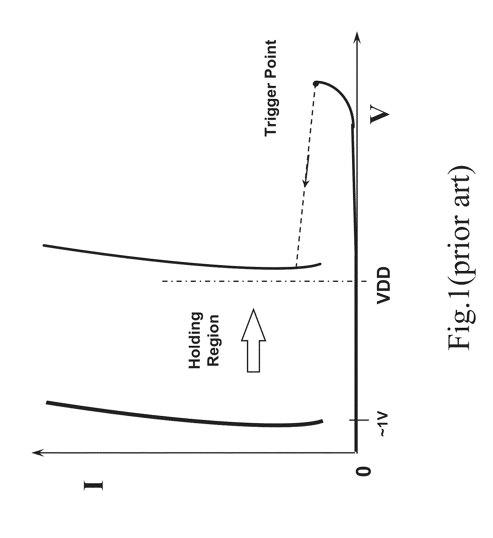
However, because the holding voltage of the SCR device is smaller than the supply voltage (for example, supply voltage of 3.3V), the SCR device is susceptible to latch-up issue during normal circuit operating condition.
The SCR device may be accidentally triggered on by the external noise pulses while the IC is in the normal operating condition.
The latch-up phenomena often leads to IC function failure or even destruction.
Therefore, the SCR device with such designs is susceptible to latch-up issue during normal circuit operating condition.
However, such designs are complicated and the holding voltage can be adjusted with only a small range.

Method used


Image

  • Silicon-controlled-rectifier with adjustable holding voltage
  • Silicon-controlled-rectifier with adjustable holding voltage
  • Silicon-controlled-rectifier with adjustable holding voltage

Examples


first embodiment

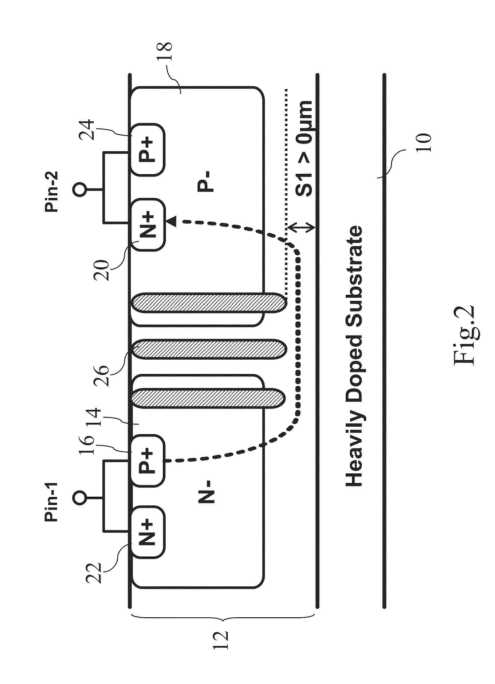
[0016]Refer to FIG. 2. the present invention comprises a heavily doped semiconductor substrate 10 used as a heavily doped semiconductor layer, wherein the heavily doped semiconductor substrate 10 is an N-type heavily doped substrate or a P-type heavily doped substrate. An epitaxial layer 12 is formed on the heavily doped semiconductor substrate 10. A first N-type well 14 is formed in the epitaxial layer 12, and a first P-type heavily doped area 16 is formed in the first N-type well 14. The first N-type well 14 is exemplified by a lightly doped N-type well. A first P-type well 18 is formed in the epitaxial layer 12, and a first N-type heavily doped area 20 is formed in the first P-type well 18. The first P-type well 18 is exemplified by a lightly doped P-type well. Besides, a second N-type heavily doped area 22 is formed in the first N-type well 14, and the first P-type heavily doped area 16 and the second N-type heavily doped area 22 are coupled to the first pin. A second P-type hea...

second embodiment

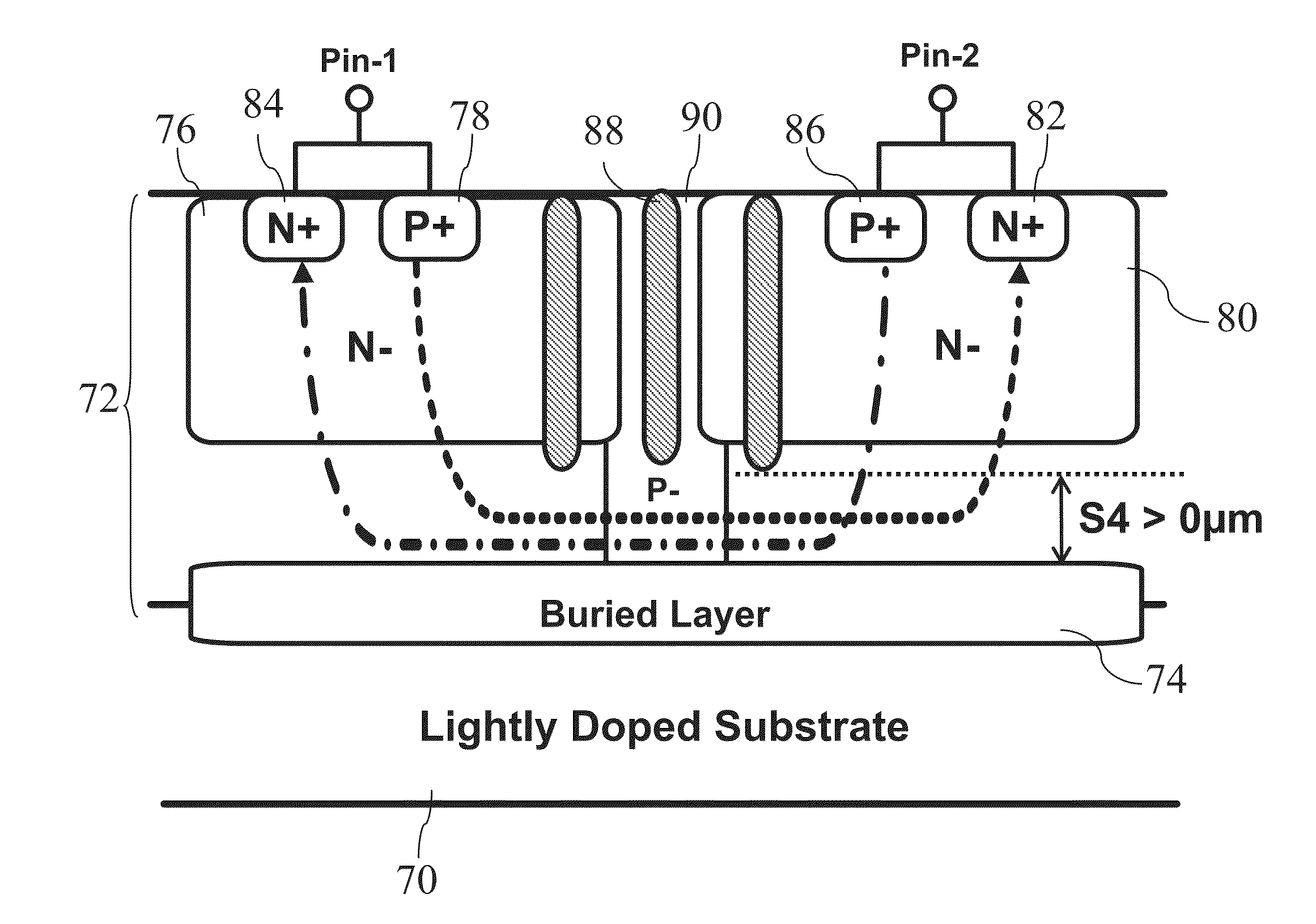
[0018]Refer to FIG. 4. the present invention comprises a lightly doped semiconductor substrate 28, such as an N-type lightly doped substrate or a P-type lightly doped substrate. An epitaxial layer 30 is formed on the lightly doped semiconductor substrate 28. A heavily doped buried layer 32, such as an N-type heavily doped buried layer or a P-type heavily doped buried layer, used as a heavily doped semiconductor layer is formed in the epitaxial layer 30 and the lightly doped semiconductor substrate 28, whereby a part of the epitaxial layer 30 is formed on the heavily doped buried layer 32. A first N-type well 34 is formed in the epitaxial layer 30, and a first P-type heavily doped area 36 is formed in the first N-type well 34. The first N-type well 34 is exemplified by a lightly doped N-type well. A first P-type well 38 is formed in the epitaxial layer 30, and a first N-type heavily doped area 40 is formed in the first P-type well 38. The first P-type well 38 is exemplified by a ligh...

third embodiment

[0021]Refer to FIG. 5. the present invention comprises a heavily doped semiconductor substrate 48 used as a heavily doped semiconductor layer, wherein the heavily doped semiconductor substrate 48 is an N-type heavily doped substrate or a P-type heavily doped substrate. An epitaxial layer 50 is formed on the heavily doped semiconductor substrate 48. A first N-type well 52 is formed in the epitaxial layer 50, and a first P-type heavily doped area 54 is formed in the first N-type well 52. The first N-type well 52 is exemplified by a lightly doped N-type well. A second N-type well 56 is formed in the epitaxial layer 50, and a first N-type heavily doped area 58 is formed in the second N-type well 56. The second N-type well 56 is exemplified by a lightly doped N-type well. A second N-type heavily doped area 60 is formed in the first N-type well 52, and the first P-type heavily doped area 54 and the second N-type heavily doped area 60 are coupled to the first pin. A second P-type heavily d...


PUM


Abstract

In a silicon-controlled-rectifier (SCR) with adjustable holding voltage, an epitaxial layer is formed on a heavily doped semiconductor layer. A first N-well having a first P-heavily doped area is formed in the epitaxial layer. A first P-well is formed in the epitaxial layer. Besides, a first N-heavily doped area is formed in the first P-well. At least one deep isolation trench is formed in the epitaxial layer, having a depth greater than the depth of the first N-type well and located between the first P-heavily doped area and the first N-heavily doped area. A distance between the deep isolation trench and the heavily doped semiconductor layer is larger than zero.

Description

CROSS REFERENCE TO RELATED APPLICATIONS[0001]This application is a Continuation-in-Part of co-pending application Ser. No. 13 / 331,241, filed on Dec. 20, 2011, for which priority is claimed under 35 U.S.C. §120 and the entire contents of all of which are hereby incorporated by reference.BACKGROUND OF THE INVENTION[0002]1. Field of the Invention[0003]The present invention relates to a silicon-controlled-rectifier (SCR), particularly to a SCR with adjustable holding voltage.[0004]2. Description of the Related Art[0005]The electrostatic discharge (ESD) attacking has become a serious problem with the continuous narrowing of transistors in the integrated circuits. The SCR (Silicon-Controlled Rectifier) device formed by the parasitic pnp and npn bipolar transistors has been commonly used for ESD protection. Due to the low holding voltage (˜1V), the SCR device can sustain much higher ESD voltage within smaller layout area, as comparing to the other ESD protection devices (such as diode, MOS...

Claims


Application Information

Patent Timeline
IPC IPC(8): H01L29/74
CPCH01L29/7424H01L29/861H01L27/0262
Inventor LIN, KUN-HSIENCHUANG, CHE-HAOJIANG, RYAN HSIN-CHIN
Owner AMAZING MICROELECTRONICS
Learn More