
Low maintenance iron roughneck system with replaceable modular components thereof

a modular component and low maintenance technology, applied in the direction of drilling rods, drilling casings, drilling pipes, etc., can solve the problems of multiple hazards for personnel, heavy equipment, and extremely dangerous drills on the drill floor

Inactive Publication Date: 2014-10-09
BERTELSEN JEFFREY LEE
View PDF5 Cites 16 Cited by
  • Summary
  • Abstract
  • Description
  • Claims
  • Application Information

AI Technical Summary

Benefits of technology

The patent describes an automated roughneck system that can connect and disconnect drill pipes at threaded interfaces. The system includes a base module, a removable spinner module, a removable torque module, and an extension module. The spinner module automatically centers itself around the drill pipe and adjusts to different diameters, while the torque module automatically adjusts to the drill pipe's torque requirements. The extension module has two arms that connect to the base module and the spinner and torque modules, allowing the system to support itself and the drill pipes. The system also includes a control console for controlling the hydraulic power and movements of the modules. The technical effects of this system include improved efficiency in drilling and reduced risk of injury to operators.

Problems solved by technology

This equipment is quite heavy (total assembly weight is about 7800 lbs) and can be extremely dangerous on the drill floor.
Further, installing the roughneck onto the drill pipe invites multiple hazards to personnel.
Moreover, the roughneck needs frequent daily and scheduled maintenance, and it is prone to breakage.
If one part of the roughneck is damaged, the entire system is out of order, costing significant downtime.
The grease is used to try and keep contaminates out of the moving parts, which could cause damage.
On the current roughnecks if this periodic maintenance is not performed, component damage will ensue.
The changing or reconfiguring of the clamp dies takes time, slowing down the drilling process.
The time it takes, “connection time”, delays extraction of oil and is a significant cost to drillers.
Often this can mean up to 5 to 7 different diameter pipe handling devices such as slips, drill collars, tongs, as well as wasted time changing between these devices or changing the devices to different pipe sizes.
There is a problem if the pipe is not centered between the dies, the pipe can be damaged or slip out of the clamps, where one clamp die is located on each side of the pipe in a holder.
This design applies all of the force in a small area about 1″ by 5″ on either side of the pipe; if the applied force is too high in this small area it will cause the pipe to become deformed, or “egg-shaped”, damaging the pipe.
This setup also will occasionally cause the pipe to hit the edge of the dies, causing pipe damage on all pipes that are small or larger than the fixed radius between the clamps.
Either of these conditions results in lost time due to the discarding of the pipe, or increased rate of pipe joint degradation which increases operating costs.
This becomes an issue, as pressure is not distributed evenly on the clamps during the torque operations.
Further, as the clamp dies provide only two points of pressure on the pipe, and not a uniform pressure, there is the possibility of slippage and / or deformation of the pipe under intense forces (typically in upwards of 100,000 ft-lbs) applied by the clamps to hold the pipe in place.
Also this design has a major issue with the force angle changing from 90 degrees to less than 90 degrees as the cylinder in the torque module rotates around the torque arc.
So the torque accuracy of this conventional torque module design is limited, it will never yield a true torque and it cannot be compensated for due to the fact the operator does not know the required amount of rotation to achieve the desired torque.
This conventional hydraulic cylinder design in a torque module is also limited on break and make operations.
This is due to the fact that a cylinder puts out less force in a retract operation then it does in an extension operation due to the loss of area on the rod side of the cylinder.
This limitation will cause what is referred to as the “breakout operation” (i.e., disconnect or breaking of the pipe joints one from the other) to be a two-step torque process instead of a single step.
Moreover, the 37 degree limitation can also cause the torque process to require multiple movement steps, as a torque head rotation may require greater than a 37 degree movement on the pipe with the clamp.

Method used


Image

  • Low maintenance iron roughneck system with replaceable modular components thereof
  • Low maintenance iron roughneck system with replaceable modular components thereof
  • Low maintenance iron roughneck system with replaceable modular components thereof

Examples


Embodiment Construction

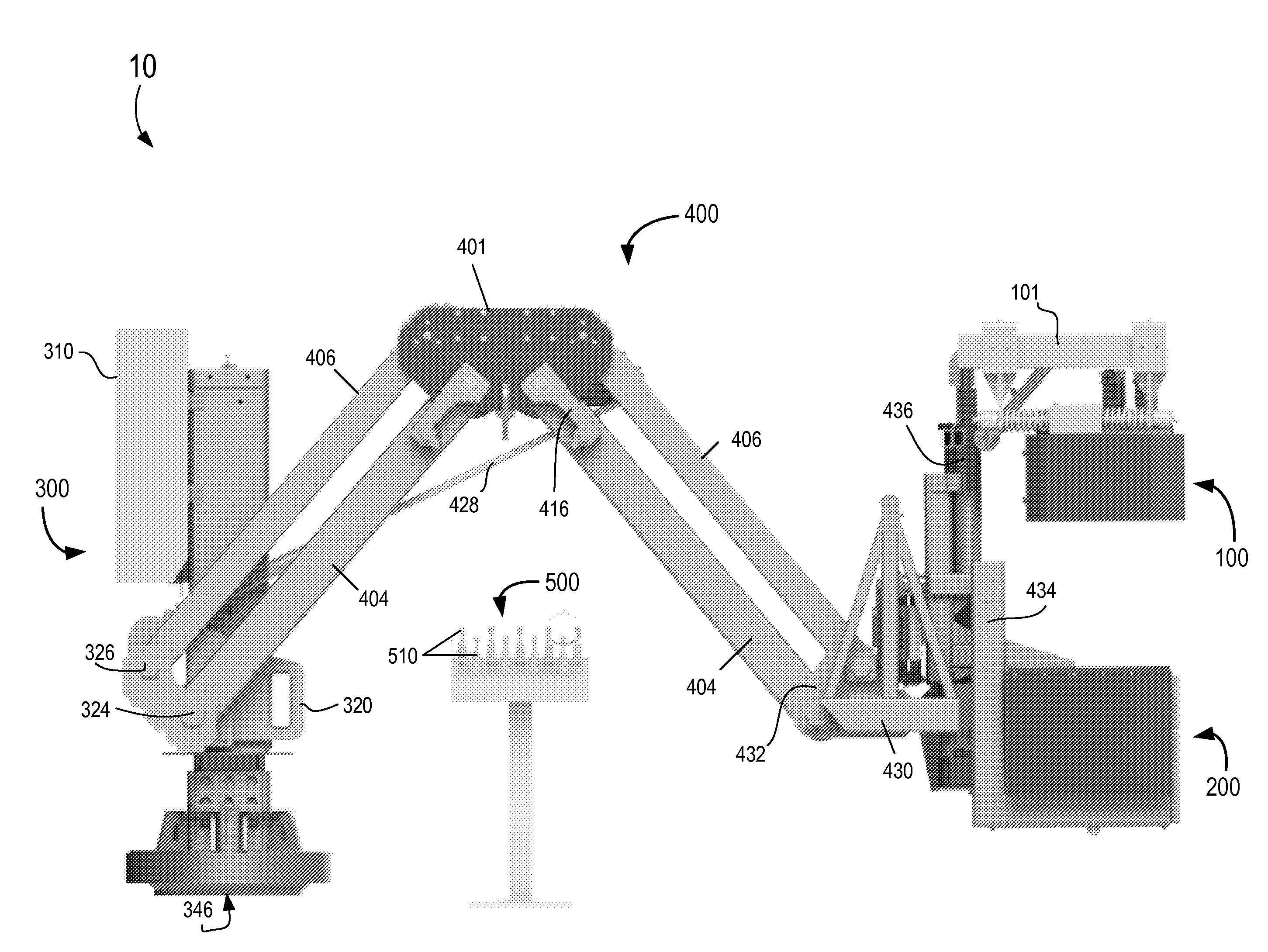
[0043]As to be described hereafter, an example embodiment is directed to a greaseless, automated, low maintenance iron roughneck system with detachable modular components thereof. The system utilizes a modular arrangement of spinner, torque and base modules with quick disconnects at modular interfaces to speed up servicing times. The use of double-sealed bearings and o-rings in modules of the system renders the system impervious to salt exposure and eliminates zerks that would necessitate greasing at regular intervals, thus eliminating extensive servicing downtime. The system employs hydraulic over hydraulic control interlock logic for improved safety, eliminating sparck, EMI & electrical issues, providing robust environment-tolerant interfaces and no Class 1 Div 1 constraints, with a remote operator control console pedestal provided outside the hazard zone to control the system, and operating on a DC battery.

[0044]FIG. 5 is a perspective view of a automated, low maintenance iron ro...


PUM


Abstract

An automated roughneck system is described which includes a base module, a removable spinner module for spinning pipe to connect or disconnect drill pipes at threaded interfaces, which automatically self-centers itself around a drill pipe and automatically adjusts to a varied range of drill pipe diameters, a removable torque module for torqueing drill pipe and which automatically self-centers itself around a drill pipe and automatically adjusts to a varied range of drill pipe diameters, an extension module including a first plurality of extension arms that extend between a central hub of the extension module and the base module, and a second plurality of extension arms that extend between the central hub and supporting structure that supports the spinner and torque modules thereon, with each of the base, extension, spinner, and torque modules being hydraulically powered, and being controlled by controls at the remote operator control console.

Description

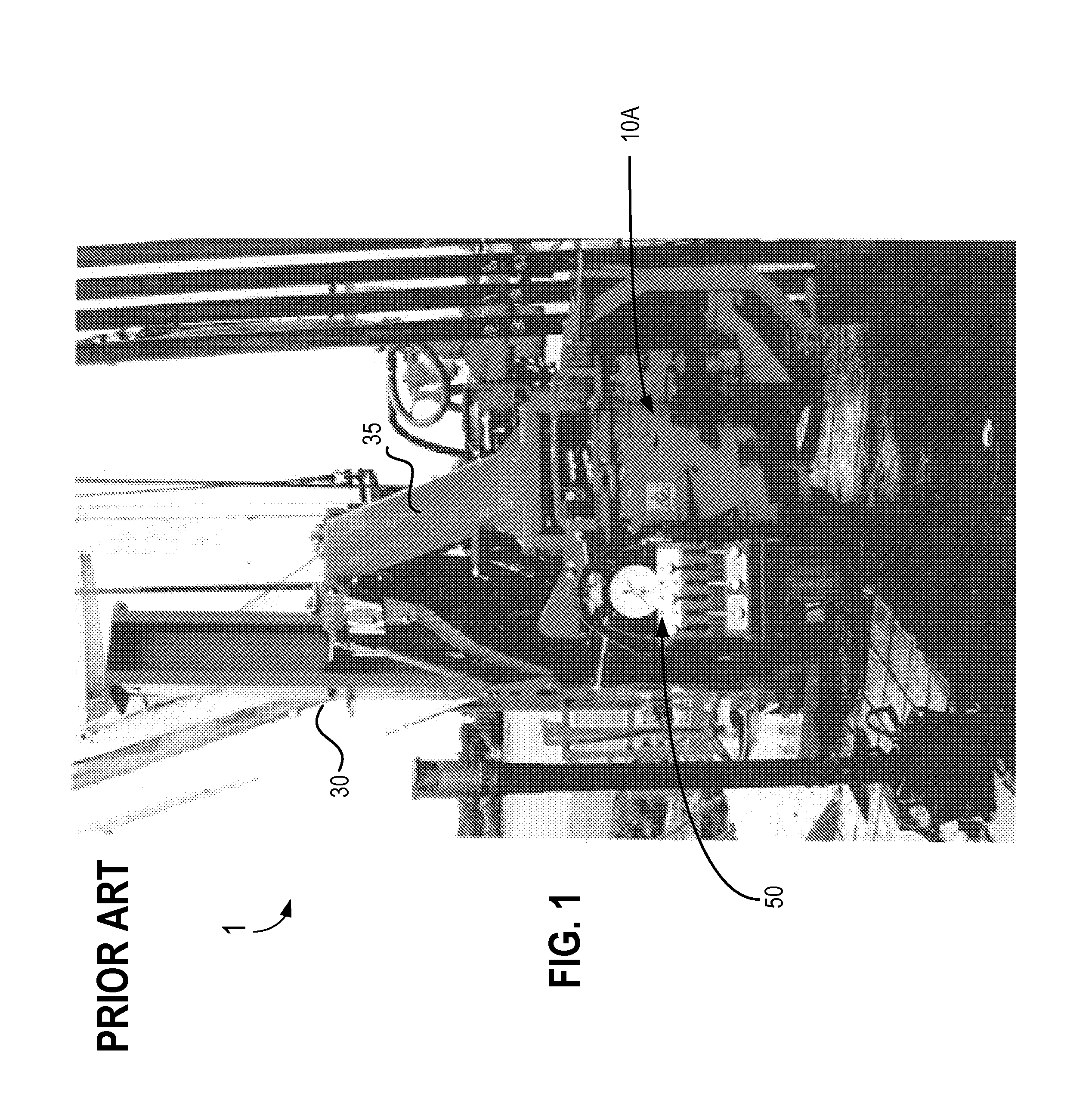
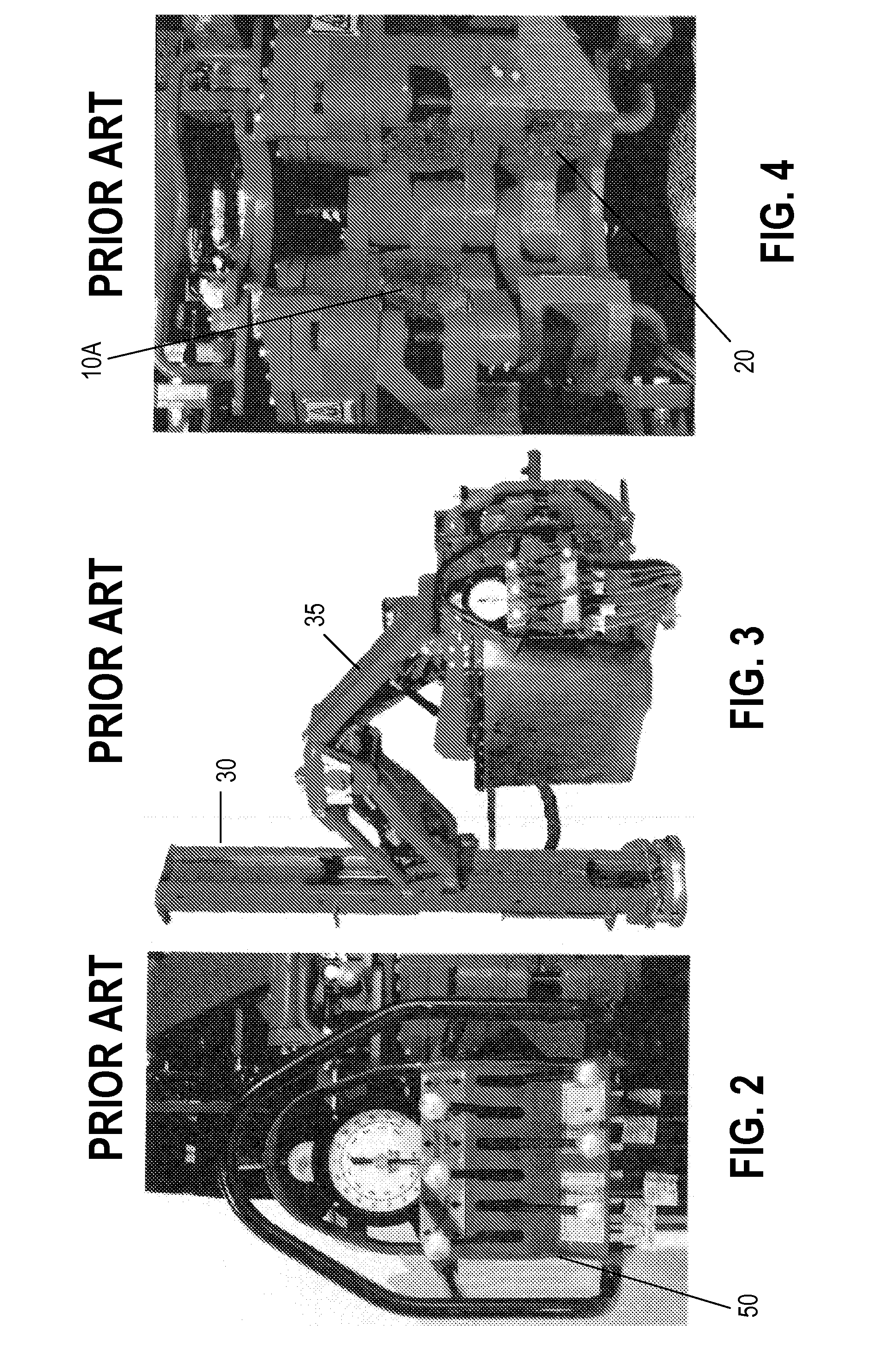
CROSS-REFERENCE TO RELATED APPLICATION[0001]The present application claims the benefit under 35 U.S.C. §119(e) of U.S. Provisional Patent Application No. 61 / 807,843 to the inventor, filed Apr. 3, 2013, the entire contents of which is hereby incorporated by reference herein.BACKGROUND[0002]1. Field[0003]Example embodiments generally relate to a low maintenance iron roughneck system with replaceable modular components thereof.[0004]2. Related Art[0005]Conventionally at an oil rig site, an iron roughneck is employed on rig floor where space is limited for drilling, drill pipe make-up and break out operations around the well center. FIGS. 1 through 4 illustrate a well known prior art iron roughneck, the ST-80C Iron roughneck manufactured by National Oilwell Varco®. Typically, the ST-80C requires a number of human operators to handle pipe make-up and break-out operations around the well center. The iron roughneck is typically installed on the drill floor utilizing either a single floor m...

Claims


Application Information

Patent Timeline
Patent Type & Authority Applications(United States)
IPC IPC(8): E21B44/00E21B15/00
CPCE21B15/00E21B44/00E21B19/168
Inventor BERTELSEN, JEFFREY LEE
Owner BERTELSEN JEFFREY LEE
Learn More