
Automated pipe tripping apparatus and methods

a pipe tripping and automatic technology, applied in the direction of drilling pipes, manufacturing tools, drilling rigs, etc., can solve the problems of damage to the wellbore, high cost of drilling rig operation, and inability to accurately determine the damage of the wellbor

Active Publication Date: 2016-12-29
ENSCO SERVICES LTD
View PDF10 Cites 11 Cited by
  • Summary
  • Abstract
  • Description
  • Claims
  • Application Information

AI Technical Summary

Benefits of technology

The present patent provides an automated pipe tripping apparatus for removing tubular members from a wellbore. The apparatus includes an outer frame and an inner frame that can be moved vertically by a lifting mechanism. The inner frame has tripping slips for receiving and supporting tubular members, and an iron roughneck for making and breaking threaded joints between tubular members. The apparatus can be positioned on a drilling floor of a drilling rig and used to remove tubular members from a wellbore. The automated control system can vary the tripping speed based on pressure within the wellbore. The technical effect of the invention is to provide a more efficient and safe method for removing tubular members from a wellbore.

Problems solved by technology

Since modern wells may become extremely deep, tripping out or tripping in operations may require a large number of threaded pipe joints to be disconnected (broken out) or connected (made up).
As the operation of a drilling rig can be extremely expensive, the need to trip in or trip out a tubular string may be a very costly operation.
Additionally, damage may be caused to the wellbore simply by removing the tubular string from or inserting the tubular string into the wellbore.
Commonly referred to as “swabbing”, these pressure fluctuations may cause, for example, reservoir fluids to flow into the wellbore or may cause instability in a formation surrounding a wellbore.

Method used


Image

  • Automated pipe tripping apparatus and methods
  • Automated pipe tripping apparatus and methods
  • Automated pipe tripping apparatus and methods

Examples


Embodiment Construction

[0016]It is to be understood that the following disclosure provides many different embodiments, or examples, for implementing different features of various embodiments. Specific examples of components and arrangements are described below to simplify the present disclosure. These are, of course, merely examples and are not intended to be limiting. In addition, the present disclosure may repeat reference numerals and / or letters in the various examples. This repetition is for the purpose of simplicity and clarity and does not in itself dictate a relationship between the various embodiments and / or configurations discussed.

[0017]For the purposes of this disclosure, tubular segment and tubular string may refer to any interconnected series of tubulars for use in a wellbore, including without limitation, a drill string, casing string, tool string, etc. as well as multiple pre-connected segments of the same including so-called pipe stands.

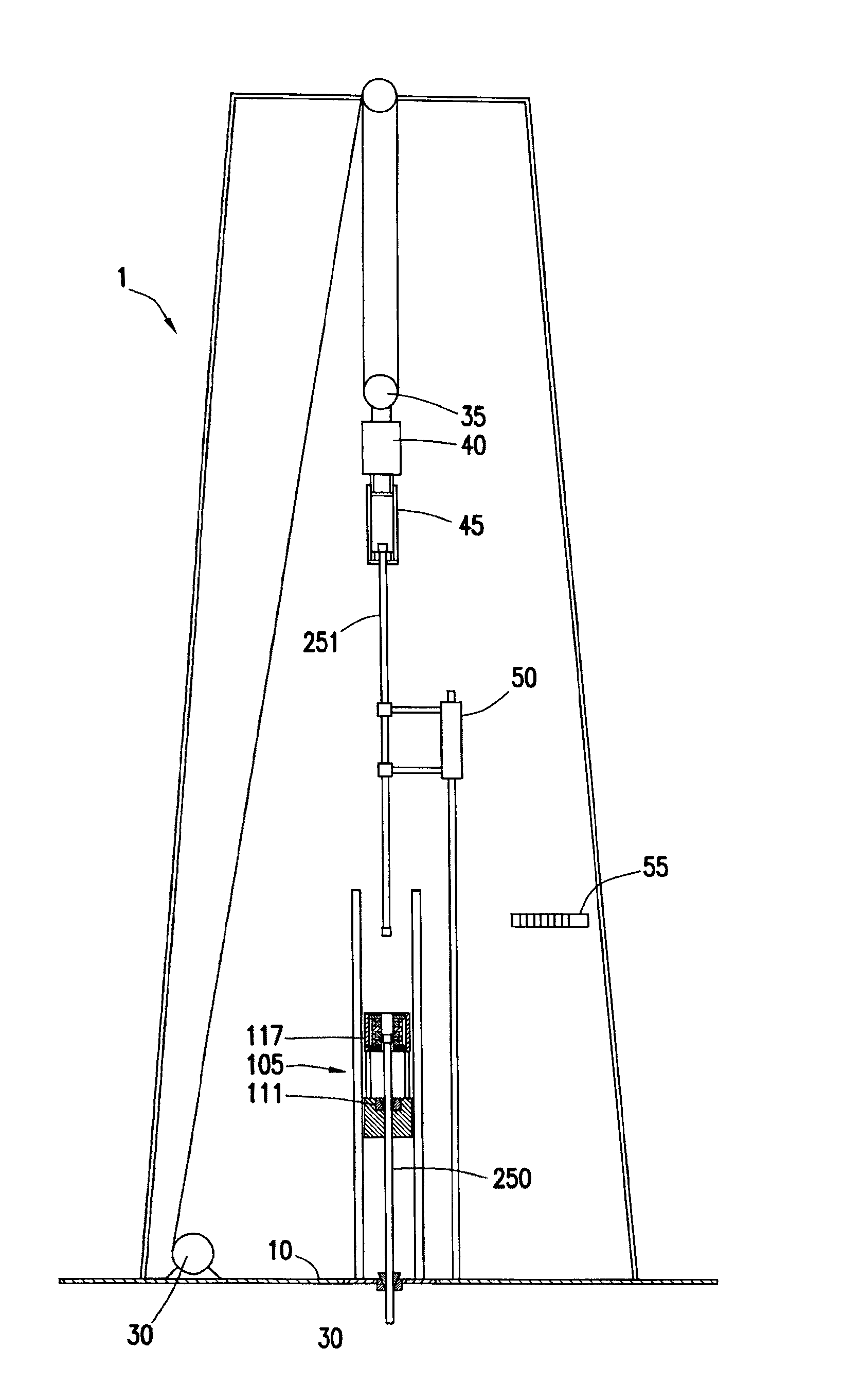
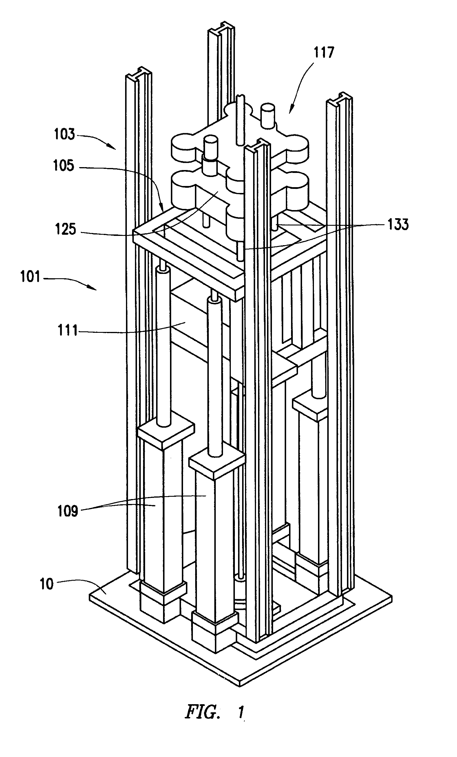
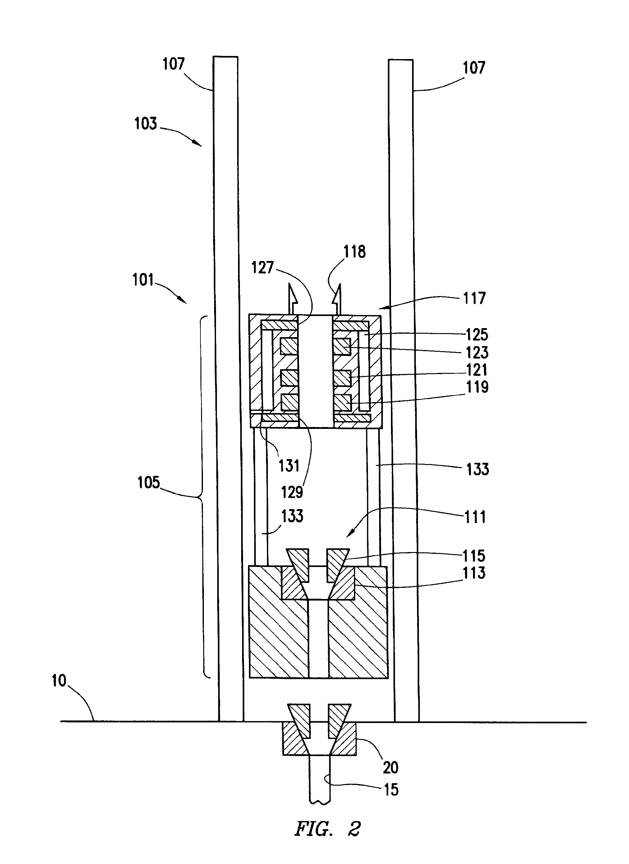
[0018]FIGS. 1 and 2 depict an automated pipe tripping...


PUM


Abstract

An automated pipe tripping apparatus includes an outer frame and an inner frame. The inner frame includes a tripping slips and iron roughneck. The automated pipe tripping apparatus may, in concert with an elevator and drawworks, trip in a tubular string in a continuous motion. The tripping slips and iron roughneck, along with the inner frame, may travel vertically within the outer frame. The weight of the tubular string is transferred between the tripping slips and the elevator. The iron roughneck may make up or break out threaded connections between tubular segments, the upper tubular segment supported by the elevator and the lower by the tripping slips. An automated pipe handling apparatus may remove or supply sections of pipe from or to the elevator. A control system may control both the automated pipe tripping apparatus and the elevator and drawworks.

Description

CROSS-REFERENCE TO RELATED APPLICATIONS[0001]The present application is a continuation of U.S. application Ser. No. 14 / 060,104, entitled “Automated Pipe Tripping Apparatus and Methods,” and filed Oct. 22, 2013, now U.S. Pat. No. 9,441,427 which issued on Sep. 13, 2016, which claims priority to U.S. Provisional Patent Application No. 61 / 716,980, entitled “Automated Pipe Tripping Apparatus and Methods”, filed Oct. 22, 2012, the entirety of which is incorporated by reference herein for all purposes.TECHNICAL FIELD / FIELD OF THE DISCLOSURE[0002]The present disclosure relates generally to handling tubular strings on a drilling rig, and in particular to making up and breaking out tubular strings during a tripping in or tripping out operation.BACKGROUND OF THE DISCLOSURE[0003]In the oil and gas industry, wells are drilled into the earth to reach reservoirs of hydrocarbons buried deep within the ground. In drilling, servicing, and completing wellbores, so-called pipe strings are utilized. Pi...

Claims


Application Information

Patent Timeline
Patent Type & Authority Applications(United States)
IPC IPC(8): E21B19/20E21B19/16E21B19/081E21B19/083E21B3/02E21B19/086E21B21/08E21B19/06E21B17/01E21B17/00E21B19/10E21B19/084
CPCE21B19/20E21B19/10E21B19/161E21B19/081E21B19/083E21B3/02E21B19/086E21B21/08E21B19/06E21B17/01E21B17/00E21B19/084B25B17/00E21B19/00E21B19/18E21B19/22E21B3/022E21B44/02
Inventor PILGRIM, RICK
Owner ENSCO SERVICES LTD
Learn More