
Raw material vaporizing and supplying apparatus equipped with raw material concentration

a technology of supplying apparatus and raw materials, which is applied in the direction of service pipe systems, process and machine control, instruments, etc., can solve the problems of affecting the quality of raw materials, the accuracy of mass flow meters fluctuating, and the response characteristics of raw material concentration are very low , to achieve the effect of stable raw material concentration, stable process treatment and high quality

Active Publication Date: 2014-10-09
FUJIKIN INC
View PDF2 Cites 13 Cited by
  • Summary
  • Abstract
  • Description
  • Claims
  • Application Information

AI Technical Summary

Benefits of technology

The present invention aims to solve problems with the regulation of raw material gas concentration in a mixed gas through a vaporizing and supplying apparatus. The current methods require expensive additional equipment and have low response characteristics, resulting in increased manufacturing costs and dimensions. The invention proposes a solution that can measure and display the raw material gas concentration in real-time, thus providing a more stable and accurate supply of the raw material. The invention utilizes a simple and low-cost device to measure the raw material gas concentration in the mixed gas, which can be used for economical control and display of the process. The technical effects of the invention include increased stability, reliability, and accuracy of the raw material gas concentration in the mixed gas.

Problems solved by technology

Therefore, there is a problem that the method is very low in response characteristics with respect to regulation of concentration and extremely low in response characteristics with respect to a decrease in concentration of the raw material gas.
Therefore, the method shown in FIG. 6 has such a problem that, irrespective of whether a type of mixed gas Gm is changed or the type is the same, a great change in a mixture ratio (concentration of raw material gas) will result in a drastic decrease in the measuring accuracy of a flow rate QS.
Still further, the change in temperature of heating the liquid raw material L0 will raise a pressure inside the closed tank 31, thereby inevitably resulting in a fluctuation in primary side pressure of the mass flow meter 36.
As a result, the mass flow meter 36 will have an error in the measured flow rate value, thus revealing a problem of decreasing the control accuracy of a flow rate and concentration of raw material gas.
Although the raw material gas supplying apparatus is able to measure a flow rate QS of the mixed gas Gm highly accurately and with high response characteristics, it has a basic problem that the mixed gas Gm is not measured for a raw material gas concentration highly accurately and cannot display a measurement value thereof.
However, a technique has not yet been developed that a raw material gas concentration of the mixed gas Gm supplied to a process chamber can be continuously and automatically measured and displayed without using a complicated and expensive concentration meter, etc., in a less expensive and economical manner.

Method used


Image

  • Raw material vaporizing and supplying apparatus equipped with raw material concentration
  • Raw material vaporizing and supplying apparatus equipped with raw material concentration
  • Raw material vaporizing and supplying apparatus equipped with raw material concentration

Examples


Embodiment Construction

[0044]Hereinafter, an embodiment of the present invention will be described with reference to the drawings.

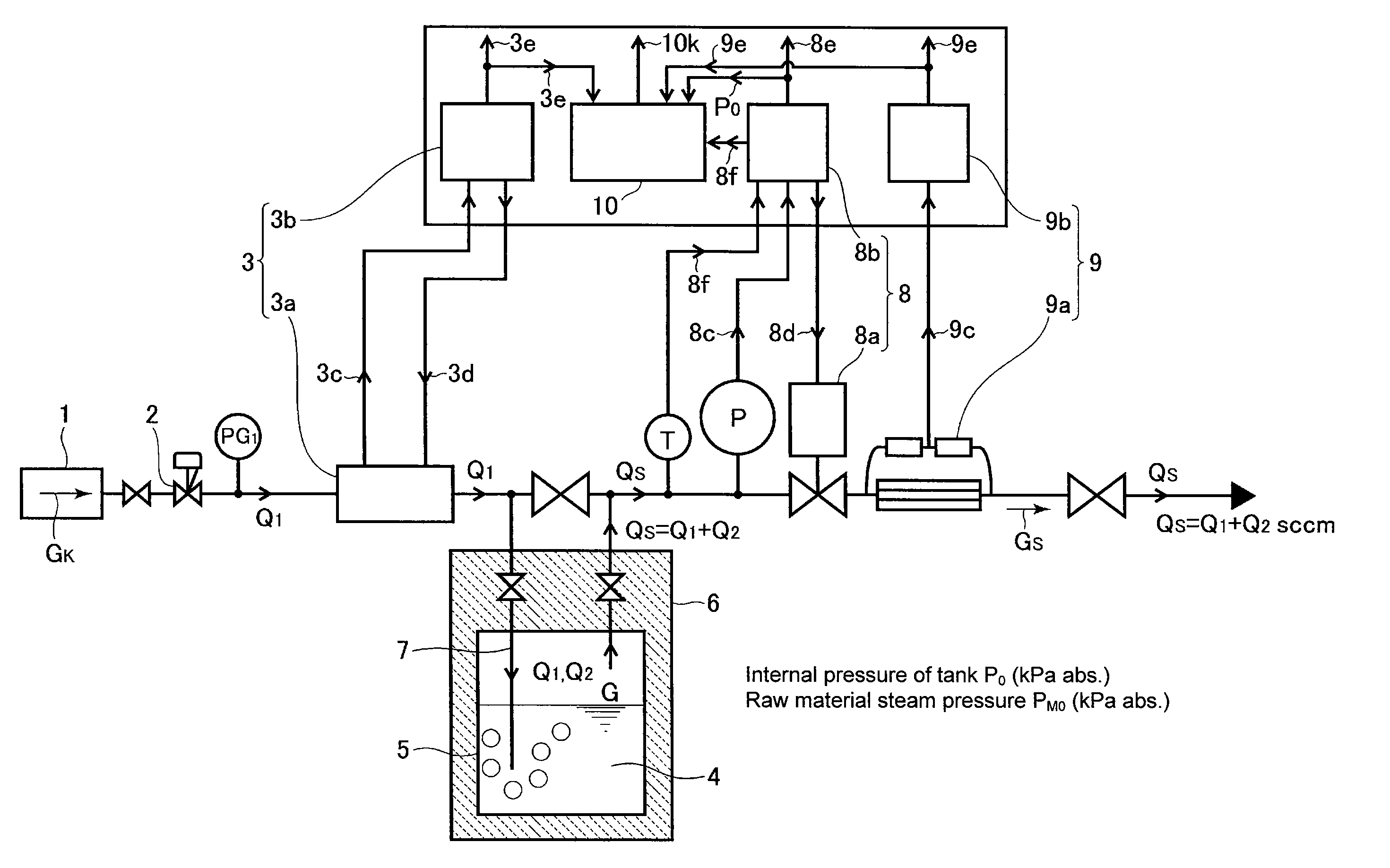
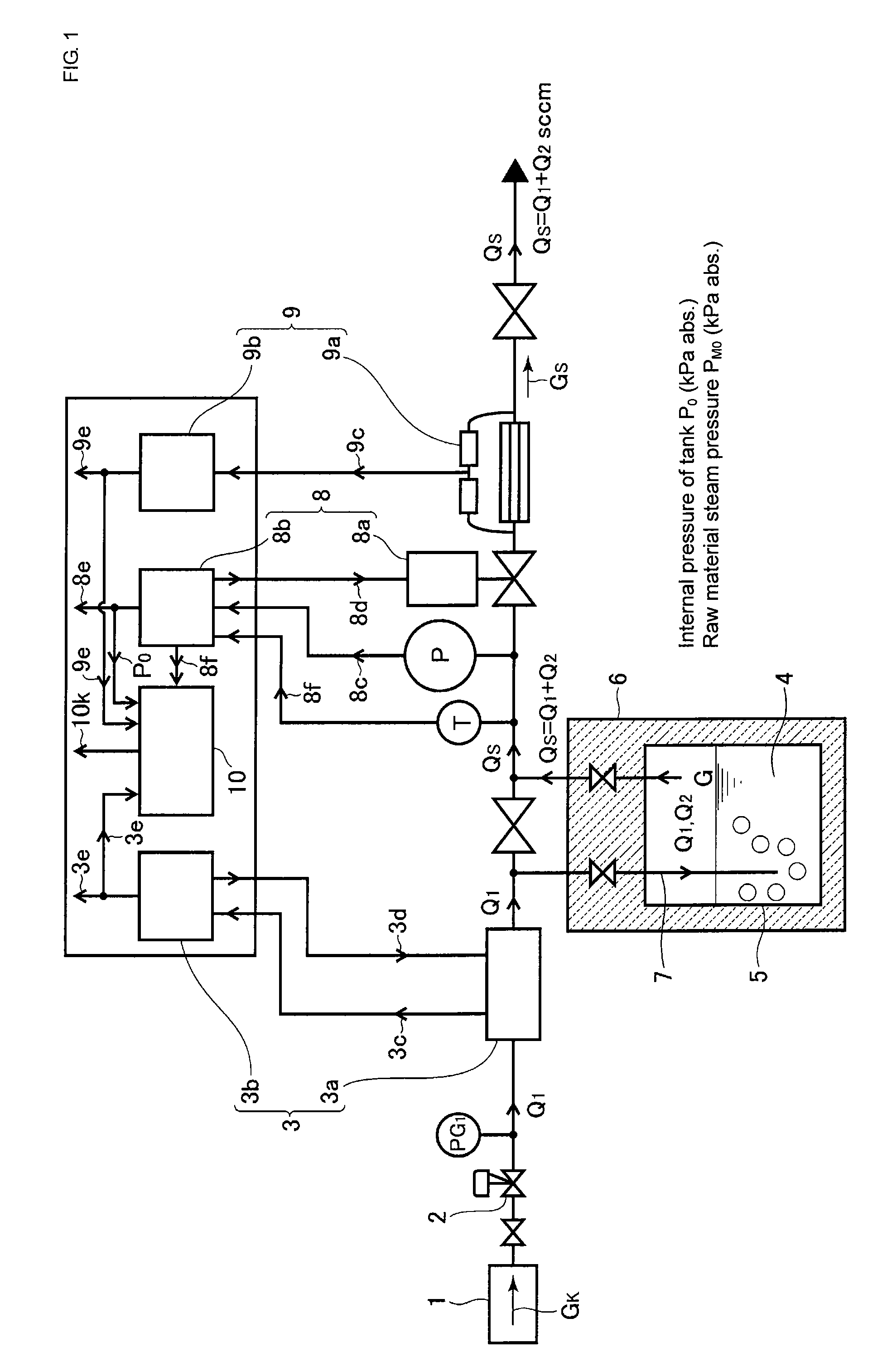
[0045]FIG. 1 is a systematic diagram which shows the structure of a raw material vaporizing and supplying apparatus equipped with a raw material concentration detection mechanism according to the first embodiment of the present invention.

[0046]In FIG. 1, reference numeral 1 denotes a carrier gas supply source, 2 denotes a decompression unit, 3 denotes a thermal type mass flow control system (mass flow controller), 4 denotes a raw material (organometallic compound (MO material), etc.), 5 denotes a source tank, 6 denotes a constant temperature unit, 7 denotes an induction pipe, 8 denotes an automatic pressure regulating device in the source tank, 9 denotes a mass flow meter, 10 denotes a raw material concentration arithmetic unit, Q1 denotes a carrier gas flow rate of Ar, etc., Q2 denotes a flow rate of the raw material saturated steam (raw material gas flow rate), QS denotes a m...


PUM

PropertyMeasurementUnit
temperatureaaaaaaaaaa
constant temperatureaaaaaaaaaa
concentrationaaaaaaaaaa

Abstract

An apparatus able to regulate a raw material concentration, in a mixed gas of carrier gas and raw material gas, accurately and stably to supply the mixed gas to a process chamber, with a flow rate controlled highly accurately, thereby detecting a vapor concentration of the raw material gas in the mixed gas easily and highly accurately and displaying the concentration in real time without using an expensive concentration meter, etc.

Description

[0001]This is a National Phase Application in the United States of International Patent Application No. PCT / JP2012 / 004559 filed Jul. 17, 2012, which claims priority on Japanese Patent Application No. 2011-194285, filed Sep. 6, 2011. The entire disclosures of the above patent applications are hereby incorporated by reference.BACKGROUND OF THE INVENTION[0002]1. Technical Field[0003]The present invention relates to an improvement in a raw material vaporizing and supplying apparatus for semiconductor manufacturing equipment using so-called metalorganic chemical vapor deposition (hereinafter, referred to as MOCVD), and, also, to a raw material vaporizing and supplying apparatus equipped with a raw material concentration detection mechanism, capable of controlling a raw material concentration of a raw material mixed gas supplied to a process chamber highly accurately and quickly, and also capable of displaying the raw material gas concentration in real time.[0004]2. Description of the Rel...

Claims


Application Information

Patent Timeline
Patent Type & Authority Applications(United States)
IPC IPC(8): F17D3/00
CPCF17D3/00C23C16/4482G05D11/135C23C16/45561Y10T137/8158H01L21/02365H01L21/28556H01L21/67017
Inventor NAGASE, MASAAKIHIRATA, KAORUHIDAKA, ATUSHINISHINO, KOUJIIKEDA, NOBUKAZUNAKAMURA, TAKESHI
Owner FUJIKIN INC
Learn More