
Identification and analysis of aircraft landing sites

a technology for aircraft landing sites and aircraft, applied in the field of identification and analysis of aircraft landing sites, can solve problems such as important flight certification issues and the inaccessibility of planned landing sites

Active Publication Date: 2014-10-02
BAE SYSTEMS PLC
View PDF1 Cites 20 Cited by
  • Summary
  • Abstract
  • Description
  • Claims
  • Application Information

AI Technical Summary

Benefits of technology

The patent describes a method for improving the correspondence between in-flight images and a modelled image of a landing site. This is done by creating a random sample of possible landing site images and comparing them with the expected mean image intensity of the landing site in a global reference frame. The method ranks each image based on how closely it matches the expected image intensity, resulting in an optimized correspondence between the in-flight images and the modelled image. This helps to improve the accuracy and reliability of identifying the location of a landing site.

Problems solved by technology

This raises important flight certification issues.
An important issue is to enable UAVs to use alternative landing sites as a result of an onboard fault or failure, which causes the planned landing site to be out of reach.

Method used


Image

  • Identification and analysis of aircraft landing sites
  • Identification and analysis of aircraft landing sites
  • Identification and analysis of aircraft landing sites

Examples


Embodiment Construction

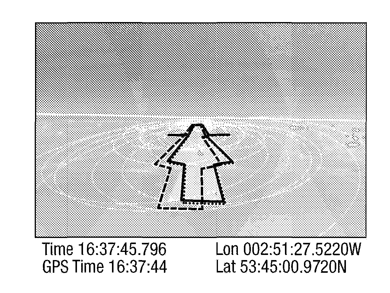
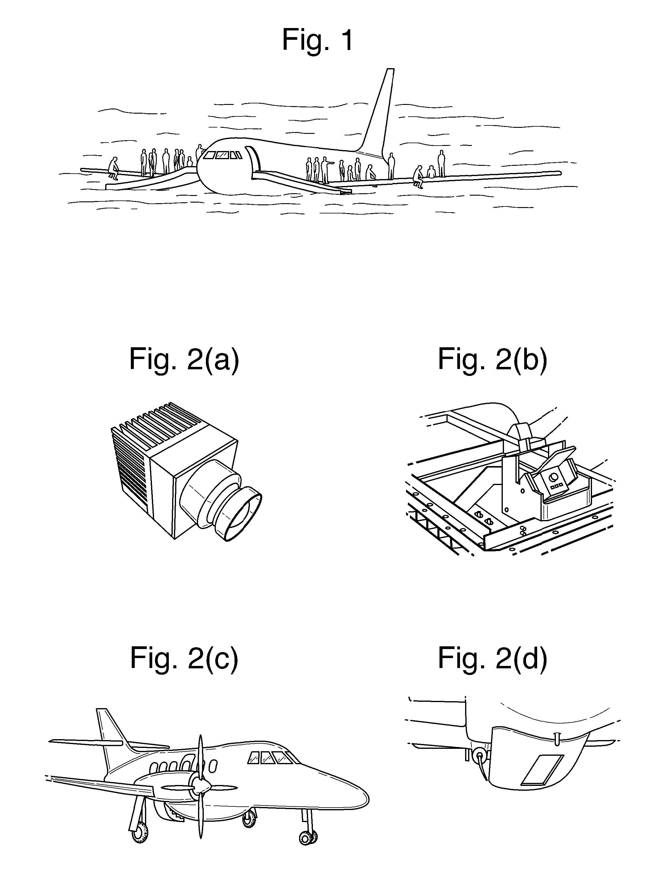
[0037]The system is being developed for the BAE Systems Military Air Solutions Flying-Test-Bed Jetstream aircraft, which acts as a surrogate UAV. During this research, the aircraft was equipped with a Thermoteknix Miricle 307 infrared camera in a fixed angled pan and tilt position installed in the undercarriage behind a Germaniun coated glass cover. The camera, camera mount, aircraft and baggage pod are shown in FIG. 3-3. This sensor is an uncooled microbolometer with a resolution of M×N=640×480 detecting wavelengths between 7-14 μm in the long-wave infrared spectrum. This is coupled to the widest angle lens available that could be installed (see Table 3). The analogue video output is digitised by a GE Series Fanuc. The digital video output is recorded using a STACK DVR2-440, which is a ruggedised solid state MPEG-2 encoder with time-stamp and GPS overlays. The video data is recorded at 25 Hz. A Honeywell Laser Inertial Navigation System (LINS) with a GARMIN GPS 496 and barometric a...


PUM


Abstract

A method and apparatus for identifying and analysing an aircraft landing site during flight is provided. The method includes the steps of using image capture means such as an infrared camera to capture in-flight images of the ground in the region of a possible landing site, using a database of computer modelled images of possible aircraft landing sites mapped to a global co-ordinate reference frame to compare the in-flight images with a modelled image of the possible landing site and optimising correspondence between the two images to obtain an in-flight image optimally mapped to the global co-ordinate reference frame. Thereafter, the landing site which corresponds to the optimally mapped in-flight image is analysed to ascertain the presence of any obstructions such as life forms, vehicles or newly erected buildings thereon.

Description

FIELD OF THE INVENTION[0001]The present invention relates to the identification and analysis of aircraft landing sites and, more particularly, to a method of identification and analysis, during flight, of such a site for the purposes of detecting obstructions on the landing site. Such a method is particularly useful when an aircraft has to make a forced landing.BACKGROUND[0002]There is an increasing demand for Unmanned Aerial Vehicles (UAVs) to enter civilian airspace. This raises important flight certification issues. These are defined by the Civil Aviation Authority (CAA) for the United Kingdom in the directorate of airspace policy. The key objective is for UAVs to demonstrate an equivalent level of safety to that of manned aircraft. An important issue is to enable UAVs to use alternative landing sites as a result of an onboard fault or failure, which causes the planned landing site to be out of reach. The CAA states that they, “may think fit to apply . . . a prohibition on flight...

Claims


Application Information

Patent Timeline
IPC IPC(8): G08G5/02G06K9/00
CPCG06K9/0063G08G5/02G08G5/0021G08G5/0086G08G5/025G06V20/176G06V20/182G06T7/30G06T19/006G01C21/20G06T2210/12G06T2207/30232G06T2207/30212
Inventor REVELL, JAMES DUNCANBUCHANAN, RODERICK
Owner BAE SYSTEMS PLC
Learn More