
Deployment Compensator for Transcatheter Valve Delivery

Inactive Publication Date: 2014-10-02
TENDYNE HLDG
View PDF0 Cites 78 Cited by
  • Summary
  • Abstract
  • Description
  • Claims
  • Application Information

AI Technical Summary

Benefits of technology

The present invention provides a device and method for reducing the force of a compressed transcatheter valve as it is being deployed in a patient. This device, called a deployment compensator, attaches to the end of a push rod and is designed to help control the valve's deployment and reduce the force required to expel it from the delivery catheter. This can make the valve deployment process safer and less traumatic for patients.

Problems solved by technology

Valvular heart disease and specifically aortic and mitral valve disease is a significant health issue in the US Annually approximately 90,000 valve replacements are conducted in the US.
While valve replacement surgery typically carries a 1-4% mortality risk in otherwise healthy persons, a significantly higher morbidity is associated to the procedure largely due to the necessity for extra-corporeal circulation.
Further, open heart surgery is often poorly tolerated in elderly patients.
This is in part reflective of the greater level of complexity associated to the native mitral valve apparatus and thus a greater level of difficulty with regards to inserting and anchoring the replacement prosthesis.
Various problems continue to exist in this field, including problems with insufficient articulation and sealing of the valve within the native annulus, pulmonary edema due to poor atrial drainage, perivalvular leaking around the install prosthetic valve, lack of a good fit for the prosthetic valve within the native mitral annulus, atrial tissue erosion, excess wear on the nitinol structures, interference with the aorta at the posterior side of the mitral annulus, and lack of customization, to name a few.

Method used


Image

  • Deployment Compensator for Transcatheter Valve Delivery
  • Deployment Compensator for Transcatheter Valve Delivery
  • Deployment Compensator for Transcatheter Valve Delivery

Examples


Embodiment Construction

Functions of the Positioning Tool

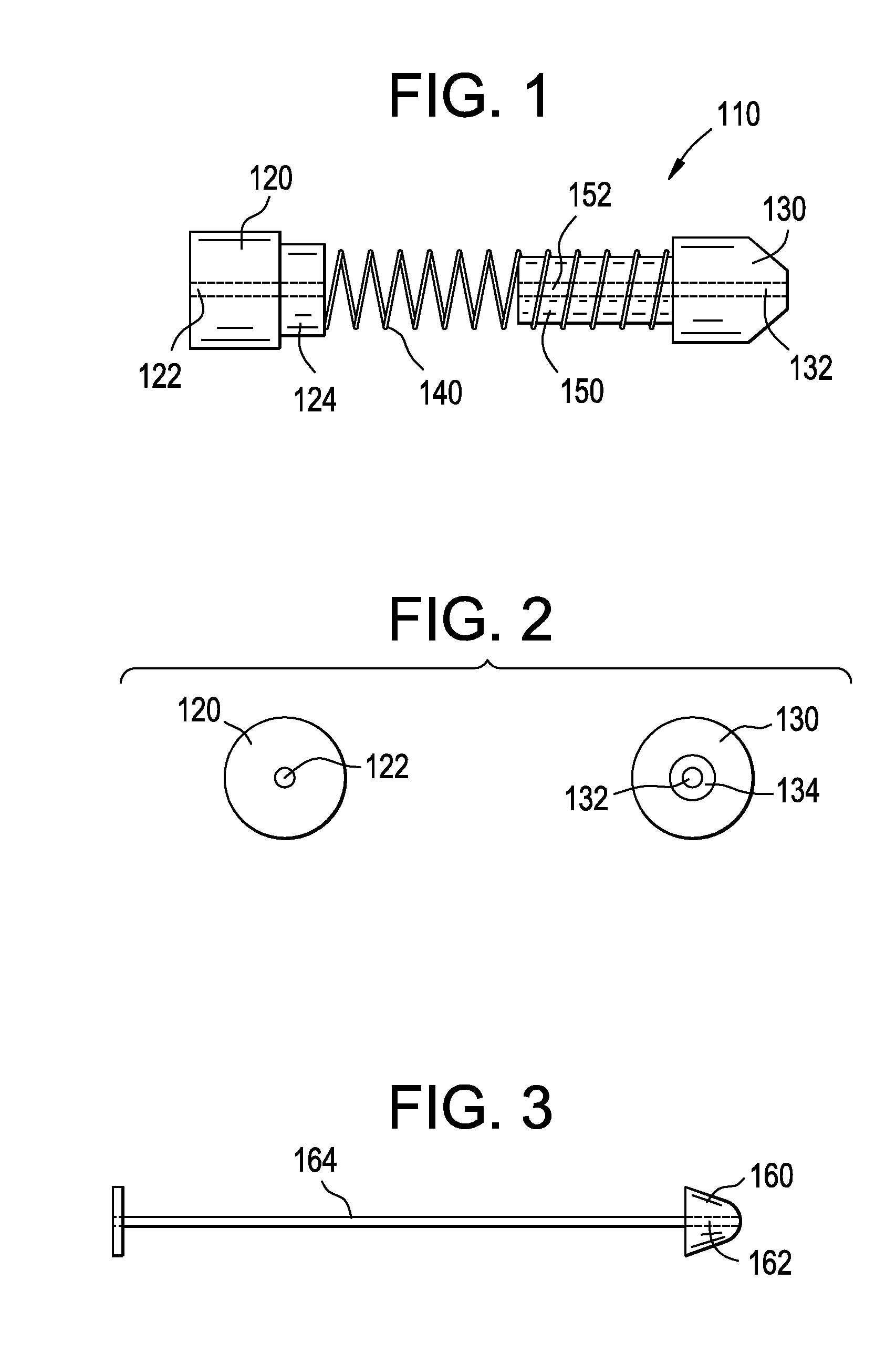
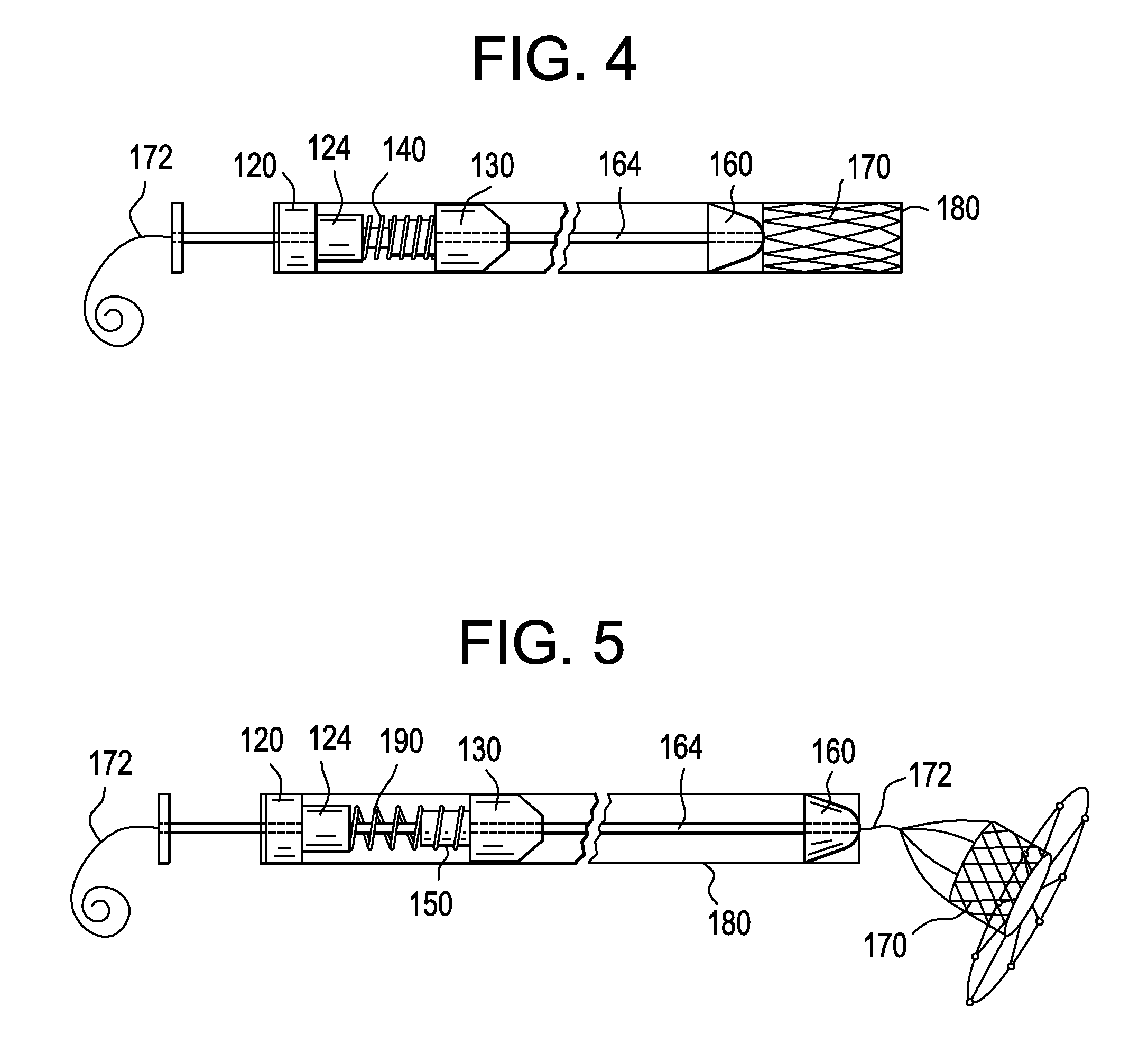
[0025]When a transcatheter valve is delivered, the compressed valve is expelled from the delivery catheter and the valve expands to its functional structure. In the case of a prosthetic mitral valve that uses an atrial cuff in combination with a ventricular tether to seat itself within the mitral annulus, when the valve is deployed into the left atrium, the valve shoots with great force from the end of the delivery catheter due to the strong compressive force that had been keeping the valve in the delivery catheter. This force is so large that it can cause significant damage to tissue, e.g. left atrium. The deployment compensator is used to pull the valve back towards the delivery catheter using an extension spring and counter-act the expelling force, this avoiding tissue damage.

Pledget / Attachment Pad

[0026]In a preferred embodiment, an epicardial pledget or attachment pad may be integrated directly into the deployment compensator, for instance on the...


PUM


Abstract

This invention relates to a deployment compensator for reducing the expelling force of a compressed transcatheter valve while it is being deployed in a patient in need thereof, and methods of use thereof.

Description

CROSS REFERENCE TO RELATED APPLICATIONS[0001]Not applicableSTATEMENT REGARDING FEDERALLY SPONSORED RESEARCH OR DEVELOPMENT[0002]No federal government funds were used in researching or developing this invention.NAMES OF PARTIES TO A JOINT RESEARCH AGREEMENT[0003]Not applicable.SEQUENCE LISTING INCLUDED AND INCORPORATED BY REFERENCE HEREIN[0004]Not applicable.BACKGROUND[0005]1. Field of the Invention[0006]This invention relates to relates to a deployment compensator for reducing the expelling force of a compressed transcatheter valve while it is being deployed in a patient in need thereof, and methods of use thereof.[0007]2. Background of the Invention[0008]Valvular heart disease and specifically aortic and mitral valve disease is a significant health issue in the US Annually approximately 90,000 valve replacements are conducted in the US. Traditional valve replacement surgery, the orthotopic replacement of a heart valve, is an “open heart” surgical procedure. Briefly, the procedure n...

Claims


Application Information

Patent Timeline
IPC IPC(8): A61F2/24
CPCA61F2/2427A61F2/2436
Inventor TEGELS, ZACHARYVIDLUND, ROBERT
Owner TENDYNE HLDG
Learn More