
Dynamic bandwidth allocation method, olt, and PON system

a bandwidth allocation and dynamic technology, applied in the field of optical communication system, can solve the problem of not defining the algorithm for dynamic bandwidth allocation, and achieve the effect of reducing power consumption and improving the efficiency of using uplink signal bandwidth

Active Publication Date: 2014-10-02
HITACHI LTD
View PDF41 Cites 23 Cited by
  • Summary
  • Abstract
  • Description
  • Claims
  • Application Information

AI Technical Summary

Benefits of technology

The present invention provides a method for dynamically allocating bandwidth to optical signals in a PON system with multiple modulation schemes. By allocating bandwidth to different ONUs in a successive manner, the number of times the optical receiver needs to switch between modulation schemes is reduced, resulting in improved efficiency of using the uplink signal bandwidth. Additionally, in cases where multiple modulation schemes are used, power consumption can be reduced by stopping the operation of circuits for unused modes.

Problems solved by technology

However, an algorithm for dynamic bandwidth allocation is not defined in Standards.

Method used


Image

  • Dynamic bandwidth allocation method, olt, and PON system
  • Dynamic bandwidth allocation method, olt, and PON system
  • Dynamic bandwidth allocation method, olt, and PON system

Examples


first embodiment

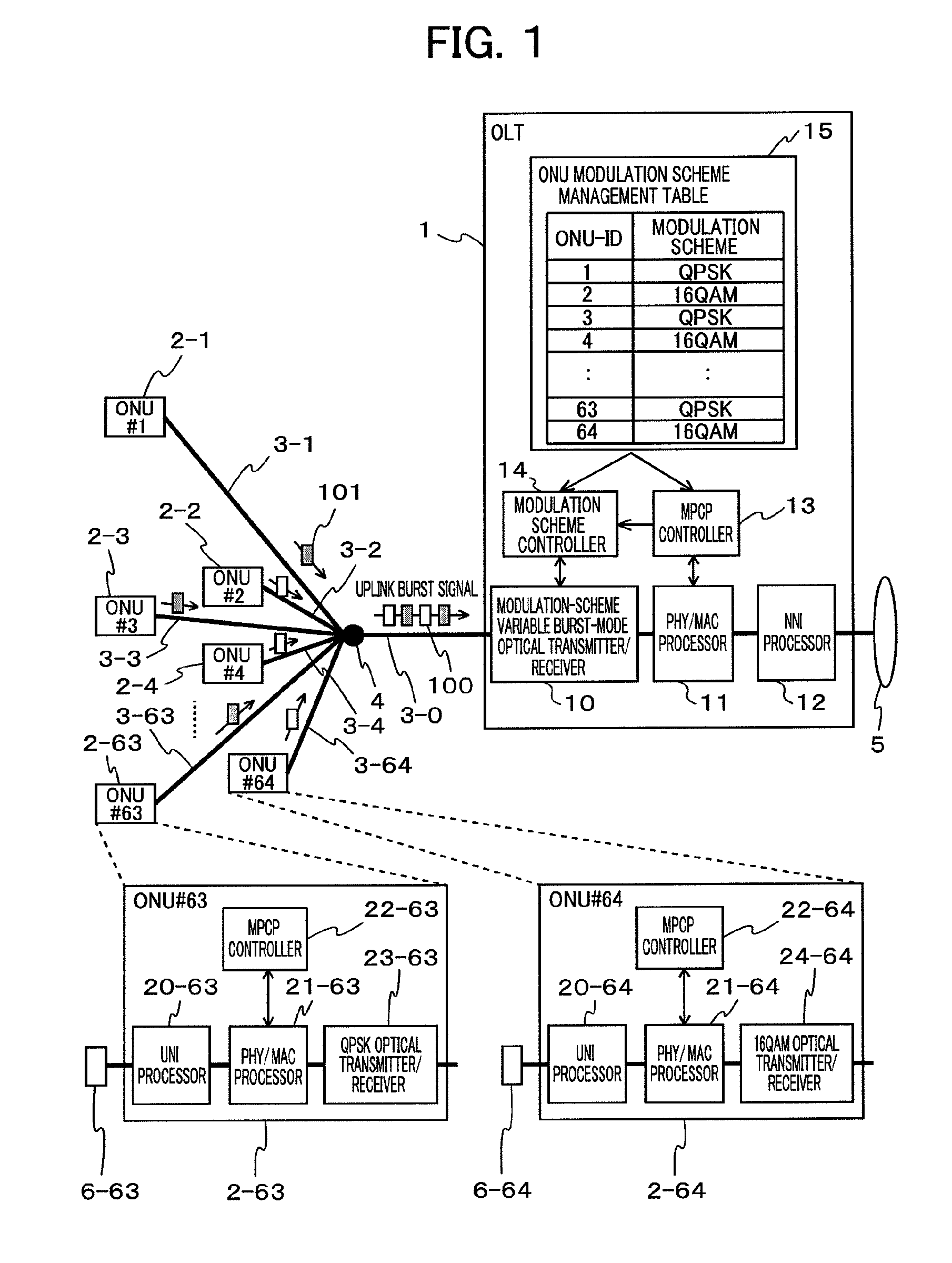
[0028]In this embodiment, an exemplary optical access system (PON system) is described in which plural kinds of ONUs for different modulation schemes coexist.

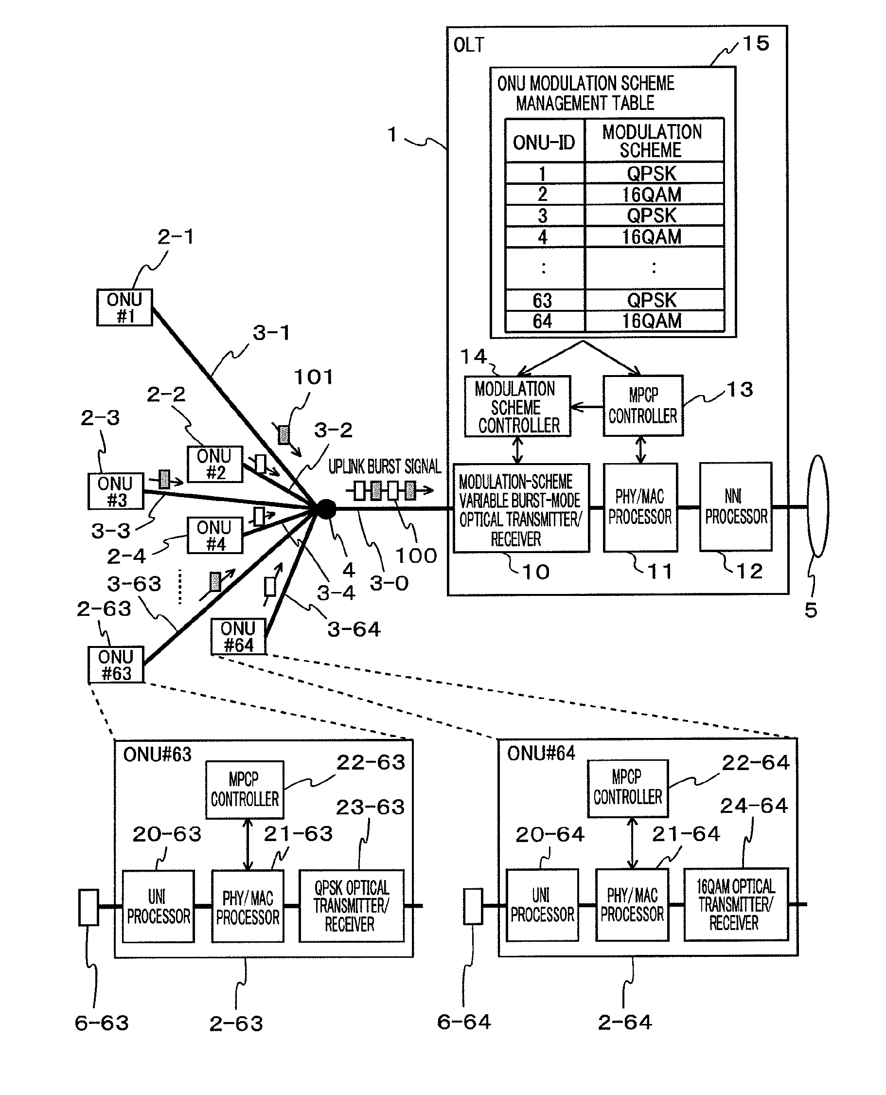
[0029]FIG. 1 is a system configuration diagram of an optical access network according to PON (PON system) including two kinds of coexisting ONUs for different modulation schemes. The optical access network of FIG. 1 includes an OLT 1 and plural ONUs 2. The OLT 1 and the ONUs 2 are connected to each other via optical fibers 3. An optical fiber 3-0 from the OLT 1 branches into 64 optical fibers 3-1 to 3-64 at an optical splitter 4 and are then connected to a total of 64 ONUs 2 (2-1 to 2-64) for a plurality kinds of modulation schemes. In this embodiment, an ONU 2-63 for QPSK and an ONU 2-64 for 16QAM are exemplified. The OLT 1 is also connected to a network 5 and the ONU 2 is connected to a terminal 6. Thus, the PON system of this example provides an environment where the terminal 6 can communicate with a given device within the ...

second embodiment

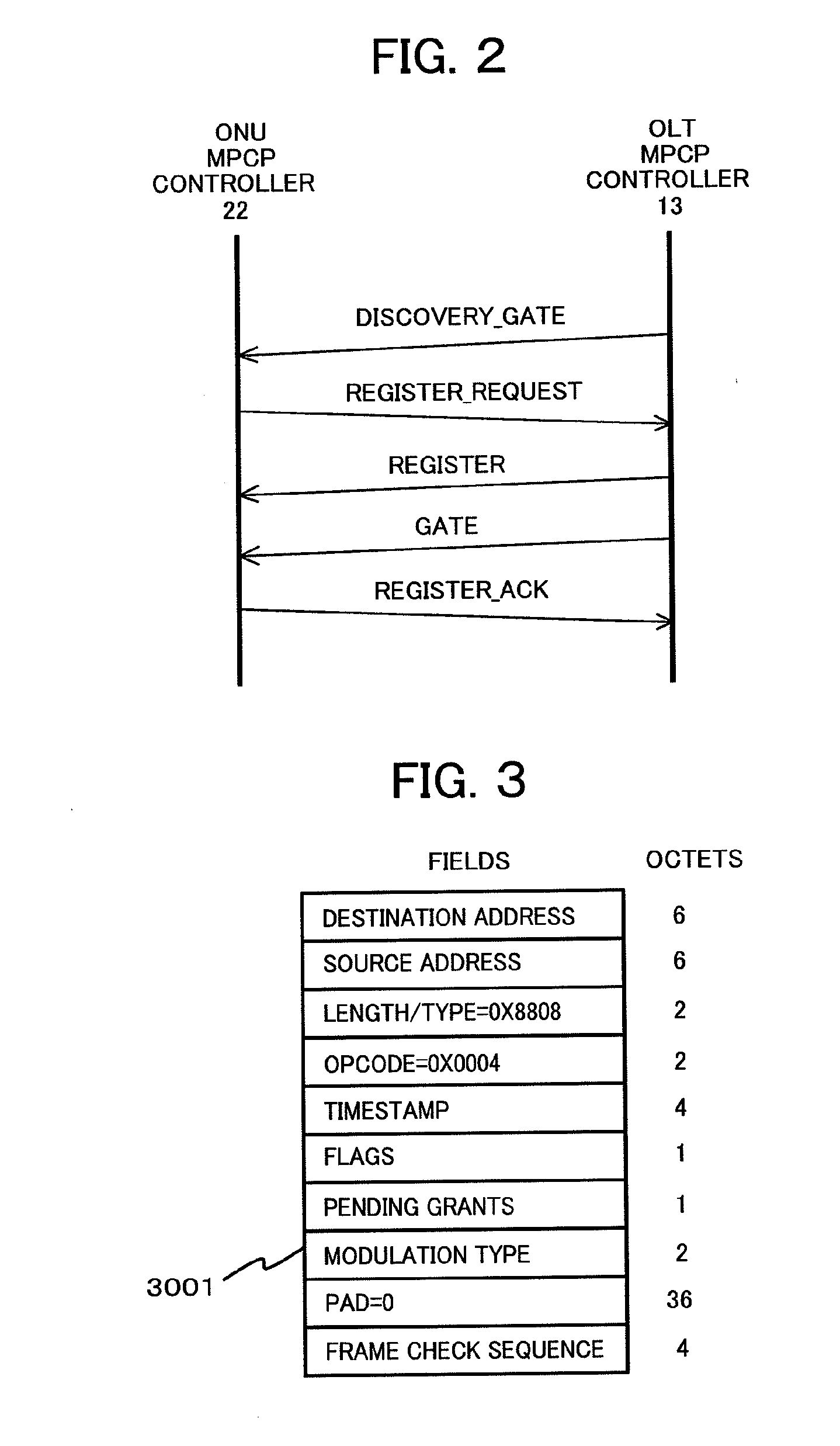
[0053]Next, the second embodiment is described in which the modulation scheme provided in the ONU is not fixed, but a single ONU can handle plural kinds of modulation schemes.

[0054]FIG. 7 is a diagram showing an exemplary entire configuration of an optical access system according to the second embodiment. As shown in FIG. 7, the OLT 1 is the same as that in the first embodiment except that the modulation schemes in the ONU modulation scheme management table 15 is dynamically changeable or variable, and therefore the description of the OLT 1 is omitted. The ONU 2-4 shown in FIG. 7 newly includes a multiple modulation scheme support optical transmitter / receiver 25-4 and a modulation scheme controller 26-4. Although not shown in FIG. 7, all the ONUs 2 may support multiple modulation schemes like the ONU 2-4 or only some of the ONUs 2 may support multiple modulation schemes.

[0055]In a case where the ONU supports multiple modulation schemes, in the discovery process described referring t...


PUM


Abstract

In a PON system in which plural kinds of modulation schemes coexist, when uplink burst signals from respective ONUs are received, the receiving efficiency degrades as the number of the times of switching of the modulation scheme increases. In an optical access (PON) system supporting plural kinds of modulation schemes, an OLT allocates bandwidths for uplink signals, i.e., transmission timings each including a transmission start time and a transmission duration, to ONUs, respectively, such that the bandwidths allocated to plural ONUs for the same modulation scheme are as successive as possible. Based on the transmission timings allocated to the respective ONUs, the OLT switches the modulation scheme of a modulation-scheme variable burst-mode optical transmitter / receiver by control of a modulation scheme controller.

Description

CLAIM OF PRIORITY[0001]The present application claims priority from Japanese patent application No. JP2013-070915 filed on Mar. 29, 2013, the content of which is hereby incorporated by reference into this application.BACKGROUND OF THE INVENTION[0002]The present invention relates to an optical communication system and, in particular, to a dynamic bandwidth allocation method which supports multiple modulation schemes, an OLT, and a PON system.[0003]A PON (Passive Optical Network) system generally employs TDMA (Time Division Multiple Access) when transmitting uplink signals from plural ONUs (Optical Network Units, i.e., customer premises equipment) to an OLT (Optical Line Terminal, i.e., station-side equipment). The OLT performs a DBA (Dynamic Bandwidth Allocation) process for allocating a transmission start time and a transmission duration, i.e., a transmission timing of each ONU, based on a transmission request from each ONU, i.e., the data size stored in the ONU. Then, the OLT notif...

Claims


Application Information

Patent Timeline
Patent Type & Authority Applications(United States)
IPC IPC(8): H04B10/27
CPCH04B10/27H04J3/1694H04Q11/0067H04Q2011/0064H04Q2011/0086
Inventor ODAKA, TOSHIYUKISUGAWA, JUNTOYODA, HIDEHIRO
Owner HITACHI LTD
Learn More