
Method for producing laminated film, polarizing plate, liquid crystal display device, and optical film

a technology of laminated film and liquid crystal display device, which is applied in the direction of instruments, polarising elements, cellulosic plastic layered products, etc., can solve the problems of reducing the thickness of the film, deteriorating the handling property, and increasing the fluctuation of the thickness, so as to reduce the thickness and reduce the thickness

Inactive Publication Date: 2014-10-02
FUJIFILM CORP
View PDF4 Cites 14 Cited by
  • Summary
  • Abstract
  • Description
  • Claims
  • Application Information

AI Technical Summary

Benefits of technology

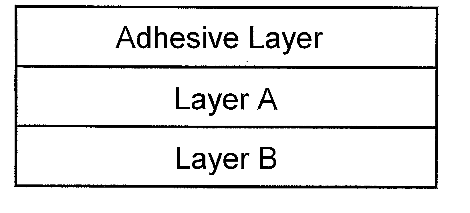
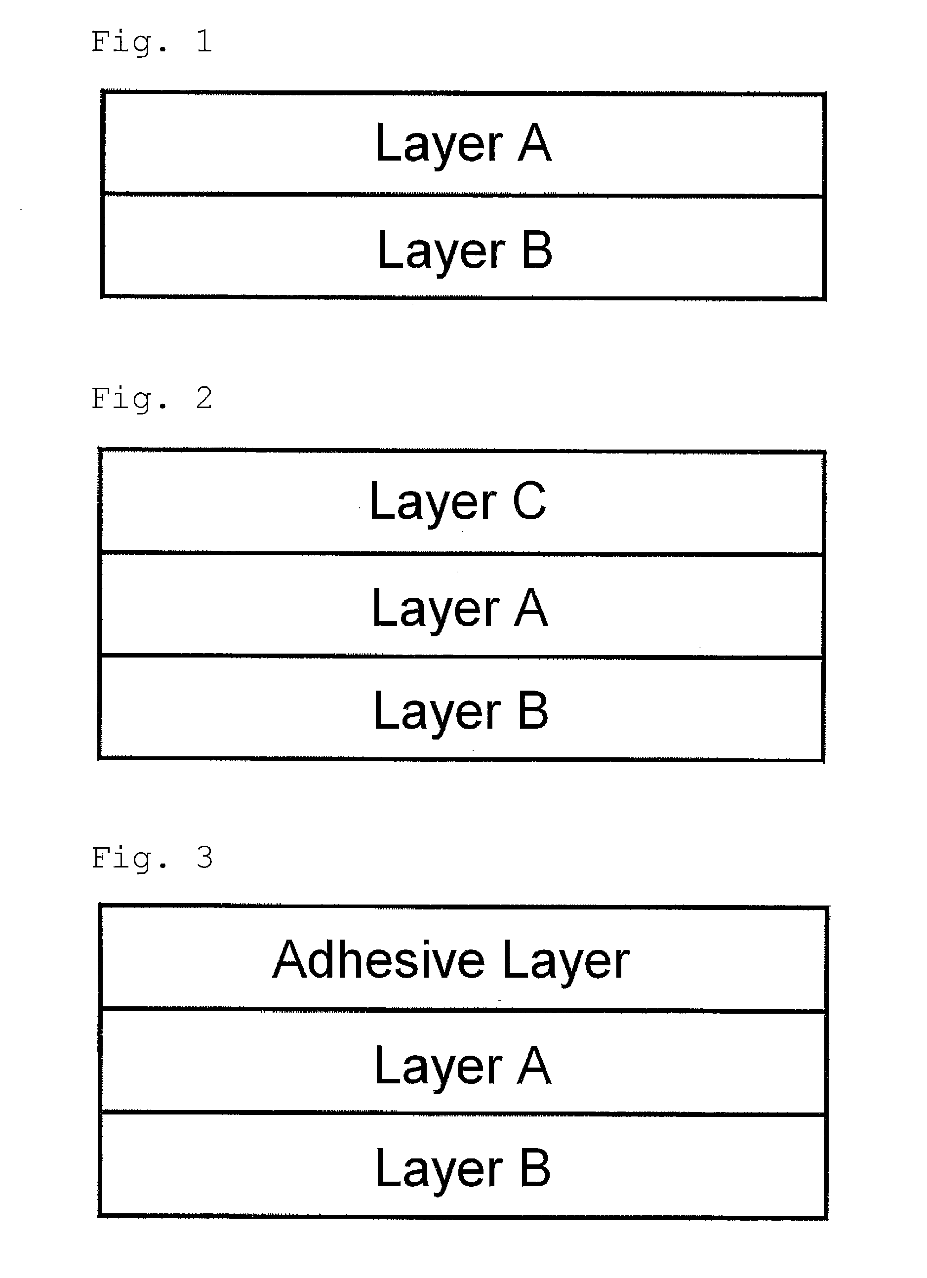
The present invention provides a new laminated film that can be used as a thin retardation film in various applications. The laminated film includes a thin retardation layer and a layer with higher tensile modulus compared to the retardation layer, which maintains good handling property during film formation. The interlayer peeling force between the two layers falls within a given range, ensuring good adhesiveness during film formation. In actual use, the thin retardation layer can be easily peeled off while the layer with higher tensile modulus remains, contributing to the reduction of the thickness of, for example, a polarizing plate and a liquid crystal display device. The invention also provides a new method for producing an optical film using the laminated film.

Problems solved by technology

Such deterioration in handling property is one factor inhibiting the reduction of the film thickness.
However, the melt casting method involves a problem of larger fluctuation in thickness of the resulting film and more considerable streak irregularity occurring in the film forming direction, compared with the solvent casting method.

Method used


Image

  • Method for producing laminated film, polarizing plate, liquid crystal display device, and optical film
  • Method for producing laminated film, polarizing plate, liquid crystal display device, and optical film
  • Method for producing laminated film, polarizing plate, liquid crystal display device, and optical film

Examples


examples

[0122]The characteristics of the present invention will be hereinunder described more specifically with reference to the examples.

[0123]Materials, amounts, proportions, and details and procedures of treatment, etc. shown in the following examples can be appropriately changed unless departing from the spirit of the invention. Therefore, the scope of the present invention is not to be construed as limited to the specific examples shown below.

[0124]Unless otherwise specified, “part” or “parts” is based on the mass.

Measurement Method

[0125]Three-dimensional refractive indices were measured by an ellipsometry (model M2000V, J.A. Woollam Co.) in which the wavelength λ was set to 550 nm.

[0126]For each film sample, a stress at 0.5% elongation in a tensile speed of 10% / min was measured using a universal tensile tester STM T 50BP (manufactured by Toyo Boldwin) in an atmosphere of 23° C. and 70% RH, whereby the tensile modulus was determined.

[0127]The interlayer peeling force was measured for e...


PUM

PropertyMeasurementUnit
thicknessaaaaaaaaaa
thicknessaaaaaaaaaa
thicknessaaaaaaaaaa

Abstract

A laminated film having a retardation layer A and a layer B that are formed through solvent co-casting is provided. The layer A has a thickness of 5 to 30 μm. The layer B has a higher tensile modulus compared to the layer A. An interlayer peeling force between the layer A and the layer B is 0.05 to 5 N / cm. The laminated film overcomes the deterioration of handling property generally occurring with the reduction of film thickness in solvent casting method.

Description

CROSS-REFERENCE TO RELATED APPLICATIONS[0001]This application is a Continuation of PCT International Application No. PCT / JP2012 / 083425 filed Dec. 25, 2012, which claims priority under 35 U.S.C. Section 119(a) to Japanese Patent Application No. 2011-283783 filed Dec. 26, 2011. Each of the above applications is hereby expressly incorporated by reference, in its entirety, into the present application.BACKGROUND OF THE INVENTION[0002]1. Field of the Invention[0003]The present invention relates to a laminated film which is used for, e.g., production of various optical films; a polarizing plate and a liquid crystal display device which include the laminated film; and a method for producing an optical film using the laminated film.[0004]2. Background Art[0005]Liquid crystal display device has been widely used as an image display device for a television, a personal computer (PC), etc., owing to its low power consumption and possibility of reduction in thickness. In recent years, the liquid ...

Claims


Application Information

Patent Timeline
Patent Type & Authority Applications(United States)
IPC IPC(8): G02B5/30G02F1/13363
CPCG02B5/305G02F2001/133638G02F1/133634G02B5/3083G02F1/13363B32B27/302B32B27/308B32B27/36B32B2307/54B32B2457/20G02B5/3033G02F2413/13B32B7/12B32B23/08B32B23/20B32B2307/418B32B2307/42B32B2457/202B32B2551/00Y10T428/24942Y10T428/2495Y10T428/24975G02F1/133638
Inventor TAKEDA, JUNNAKAYAMA, HAJIMEITO, YOJI
Owner FUJIFILM CORP
Learn More