
Tool holster for attachment to leg

a tool holder and tool technology, applied in the field of tools supporting devices, can solve the problems of not always practical, general heavyness, and general bulkiness of tools, and achieve the effects of convenient use, simple construction, and economical manufactur

Inactive Publication Date: 2014-10-02
VICTOR SCALA
View PDF9 Cites 35 Cited by
  • Summary
  • Abstract
  • Description
  • Claims
  • Application Information

AI Technical Summary

Benefits of technology

The invention is a tool holder that can be attached to a user's leg without interfering with their movements. It is simple and economical to manufacture and enhances safety at a work site to prevent injury or damage from inadvertent separation of a tool from a holster. It is convenient to use and allows the user to quickly and easily separate a tool on the holster for use or re-attachment a tool to the holster when use of the tool is no longer needed. It also allows the user to secure a bulky and heavy tool to the person without interfering with the use of a tool belt that may also be used to support or carry other materials or tools that the user may require at a work site.

Problems solved by technology

While power and air tools continue to be made more efficient and lighter in weight, they continue to be generally heavy and bulky.
However, this is not always practical since the user's hand(s) may need to perform other functions such as holding the rungs of a ladder while the user is climbing up or down the ladder.
As noted, such tools are generally heavy, particularly battery operated tools, since the batteries themselves are quite heavy.
Power tools, because of their generally large size, occupy much real estate that could otherwise be sued for smaller tools, pouches, etc.
However, prior tool holding devices fail to provide the degree of safety to the user as well as others at a work site.
This could create hazardous conditions at the work site when, for example, a user climbs up a ladder with numerous devices and tools that are secured to his person.
The prior art does not, however, show a tool holster of the type suggested that is attached directly to the leg or the thigh of the user and not directly to the belt of the user.
The prior art, accordingly, also fails to teach the use of an ancillary belt between a leg holster and the waist belt for securing the same in place.
The device disclosed, therefore, is not to safely support tools, but is simply a pivotably mounted support arm attached to a leg harness that positions at a location convenient for supporting a board, such as sheet rock, if a carpenter cannot otherwise avail himself on a support surface on which to support the board to be cut.
None teach or suggest a tool holster to be tightened or secured to the leg or around the thigh of the user.

Method used


Image

  • Tool holster for attachment to leg
  • Tool holster for attachment to leg
  • Tool holster for attachment to leg

Examples


Embodiment Construction

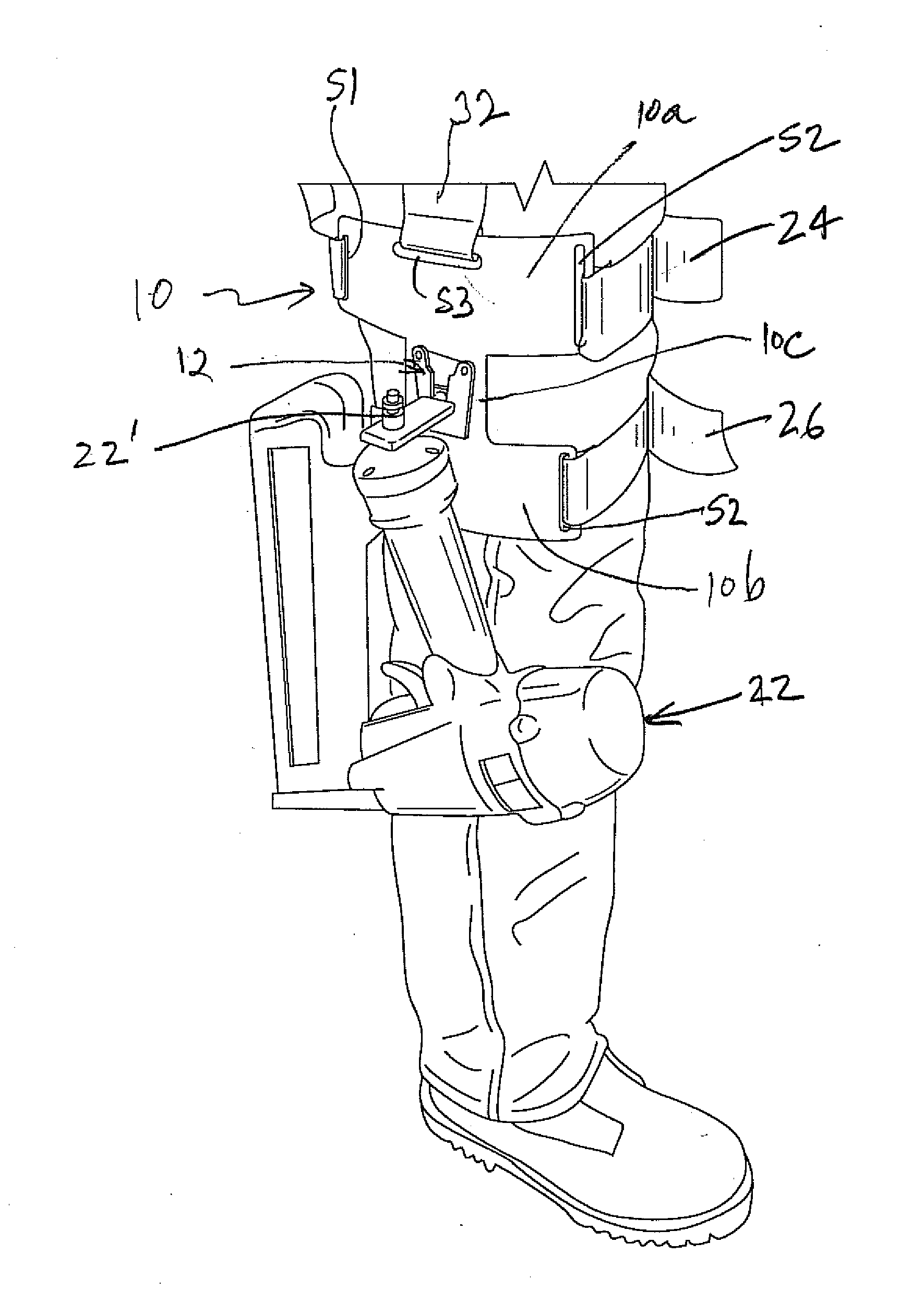
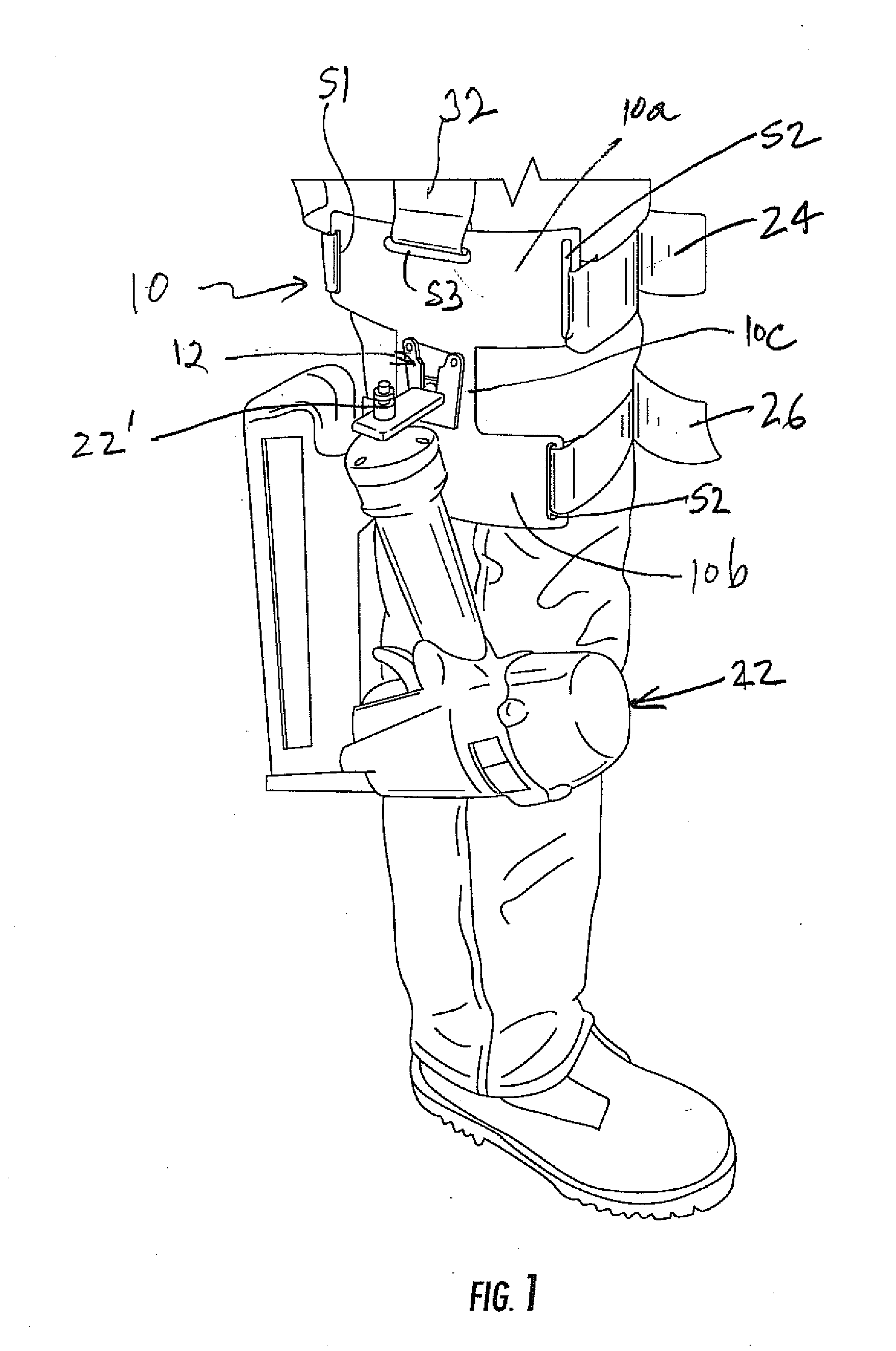
[0025]Referring to the Figures in which identical or similar parts would be designated by the same reference numerals throughout, and first referring to FIG. 1, a tool holster in accordance with the present invention is generally designated by the reference numeral 10.

[0026]The holster 10 includes two spaced substantially parallel portions 10a, 10b with a transverse portion 10c to generally form a H-support member. The portions 10a-10c can be formed of any suitable material that is strong, such as leather, plastic or the like. The portions 10a-10c may be flexible to conform to the shape of the user's leg or can be more rigid members that are molded to provide the appropriate curvature to generally conform to the external shape of the thigh on which the holster will typically be mounted.

[0027]Each parallel portion 10a, 10b is provided with a generally elongated slot S1, S2 at opposite ends thereof dimensioned to receive straps or belts to be described. The upper portion 10a is additi...


PUM


Abstract

A tool holster includes a connector of a clip is provided for detachably securing a tool to a leg harness. A fastener stud is attachable to the tool. The holder rotatably receives the fastener stud for movements between a first angular orientation that permits the fastener stud to be selectively received and removed from the holder and a second angular orientation that prevents the fastener stud received within the holder from being separated or removed from the holder. A support member is attached to the fastener stud for sharing common rotational movements therewith and connectable to a tool to be supported. The support member is oriented to move the fastener stud to the second angular orientation only when the tool is freely suspended on the holder under the action of gravity regardless of the position or orientation of the user's leg.

Description

BACKGROUND OF THE INVENTION[0001]1. Field of the Invention[0002]This invention generally relates to devices for supporting tools on the body of a user and, more specifically, to a tool holster for attachment to a thigh of a user.[0003]2. Description of the Prior Art[0004]While power and air tools continue to be made more efficient and lighter in weight, they continue to be generally heavy and bulky. Contractors frequently have a need to transport such tools to locations where work is in progress. This may require carrying a tool with one or both hands. However, this is not always practical since the user's hand(s) may need to perform other functions such as holding the rungs of a ladder while the user is climbing up or down the ladder.[0005]As battery powered tools continue to proliferate and the variety such tools increases, contractors increasingly rely on such tools and, at times, actually need to employ more than one such tool at a work site. Numerous devices have been proposed ...

Claims


Application Information

Patent Timeline
Patent Type & Authority Applications(United States)
IPC IPC(8): A45F5/00
CPCA45F5/00A45F2005/002A45F2005/008A45F2200/0575B25H3/006
Inventor VICTOR, SCALA
Owner VICTOR SCALA
Learn More