Flaring device for a tubular member
- Summary
- Abstract
- Description
- Claims
- Application Information
AI Technical Summary
Benefits of technology
Problems solved by technology
Method used
Image
Examples
Embodiment Construction
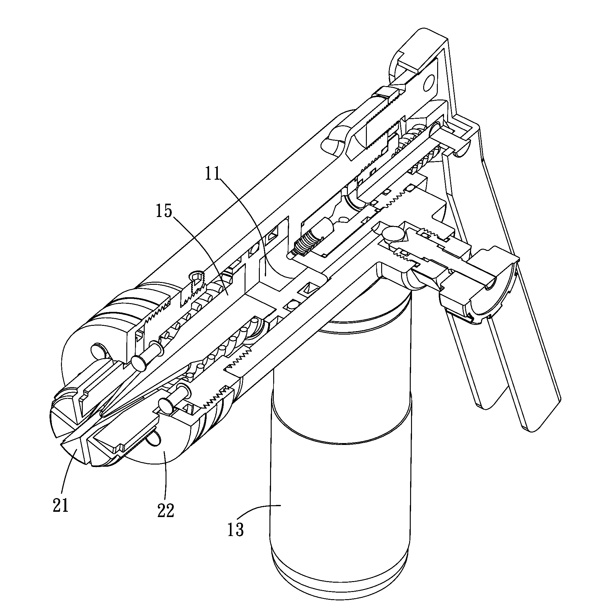
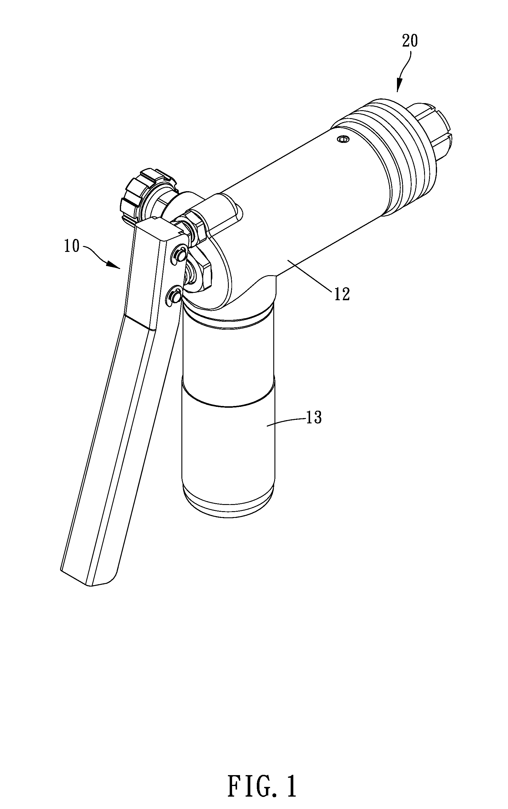
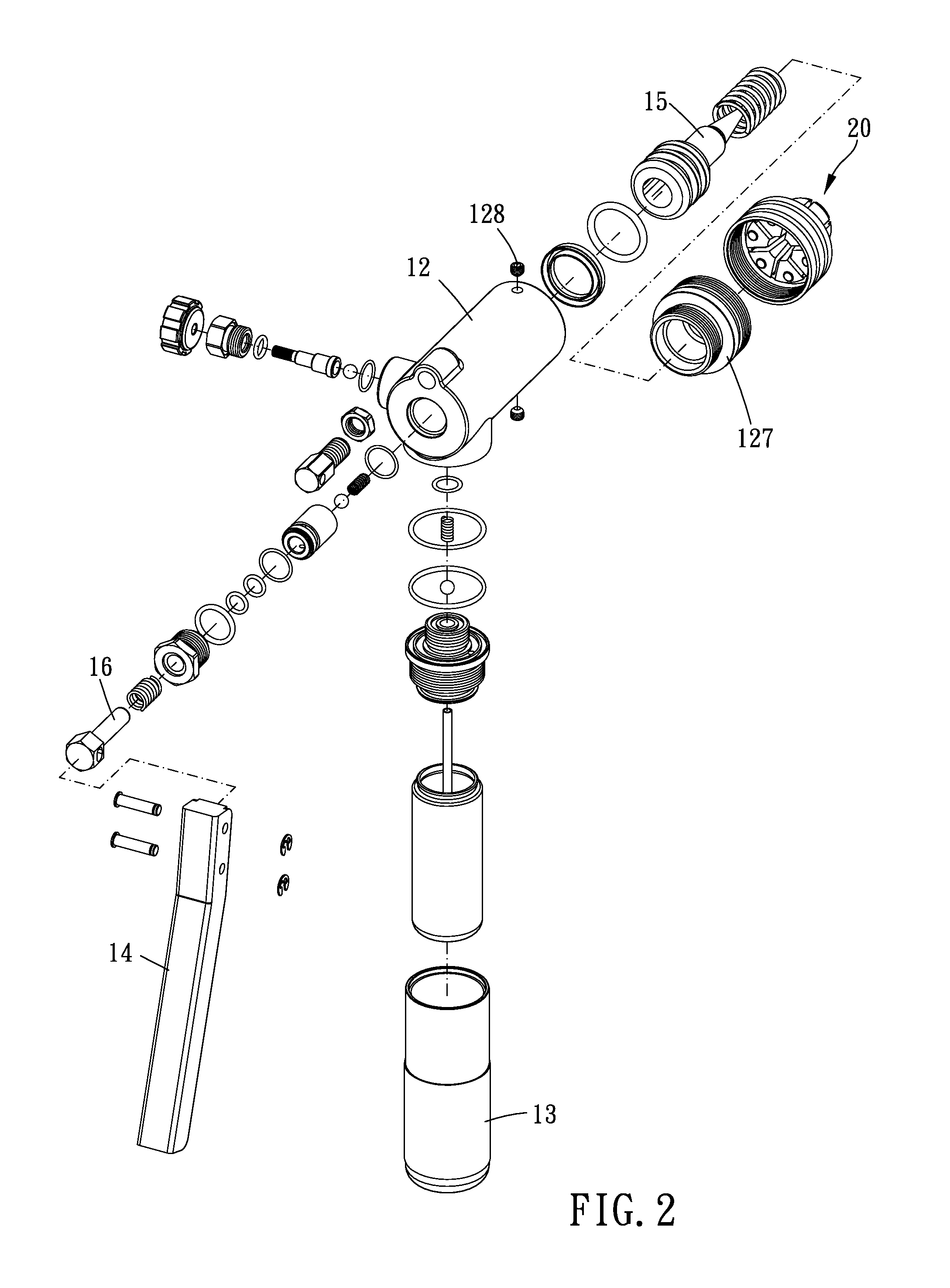
[0021]FIGS. 1-4 show a flaring device according to a preferred embodiment of the present invention. The flaring device is used to flare a hollow malleable tubular member and includes a hydraulically powered assembly 10 and a die set 20.
[0022]The hydraulically powered assembly 10 includes a main body 12 having a cylinder 11, a liquid container 13, a lever 14 and a piston member 15 received in the cylinder 11.
[0023]The main body 12 has an axis 121, a first end 122 and a second end 123. The first end 122 and the second end 123 are located on the axis 121 and are opposite to each other. The liquid container 13 is traverse to a direction in which the axis 121 extends (such as vertical to the axis 121) and radially extended from the main body 12, so that the flaring device could provide a proper hold length for operating with one hand. Clearly, the liquid container 13 controllably communicates with the cylinder 11 in fluid flowing relationship. A fluid passage 124 is formed between the cy...
PUM
| Property | Measurement | Unit |
|---|---|---|
| Time | aaaaa | aaaaa |
Abstract
Description
Claims
Application Information
 - R&D
- Intellectual Property
- Life Sciences
- Materials
- Tech Scout
- Unparalleled Data Quality
- Higher Quality Content
- 60% Fewer Hallucinations
Browse by: Latest US Patents, China's latest patents, Technical Efficacy Thesaurus, Application Domain, Technology Topic, Popular Technical Reports.
© 2025 PatSnap. All rights reserved.Legal|Privacy policy|Modern Slavery Act Transparency Statement|Sitemap|About US| Contact US: help@patsnap.com


