
Temperature measurement in a gas turbine engine combustor

Inactive Publication Date: 2014-09-18
SIEMENS ENERGY INC
View PDF5 Cites 46 Cited by
  • Summary
  • Abstract
  • Description
  • Claims
  • Application Information

AI Technical Summary

Benefits of technology

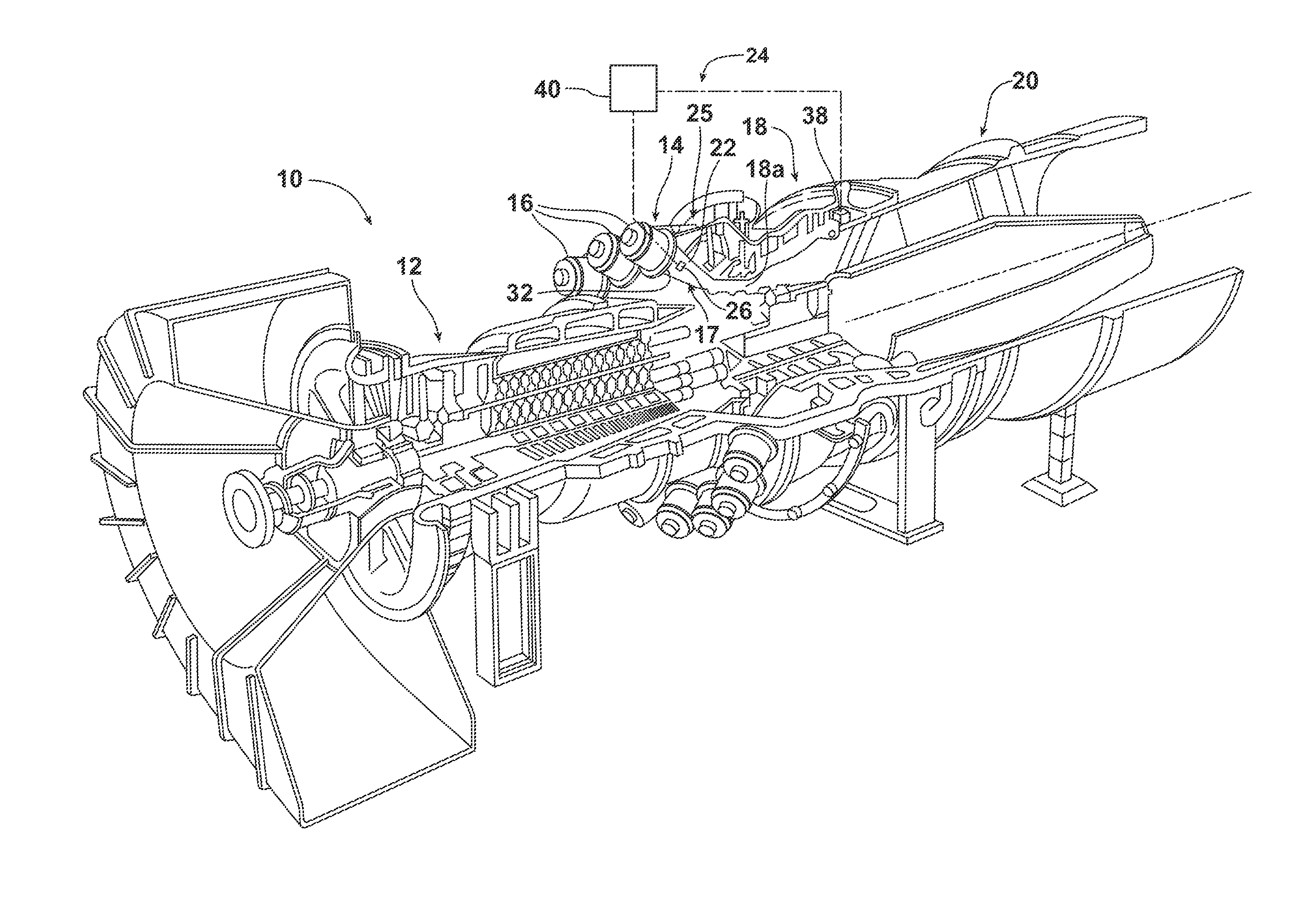
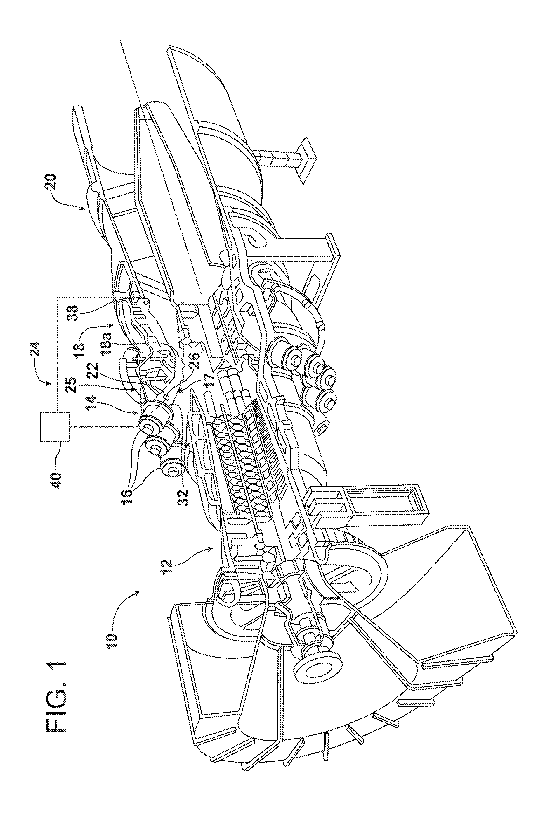
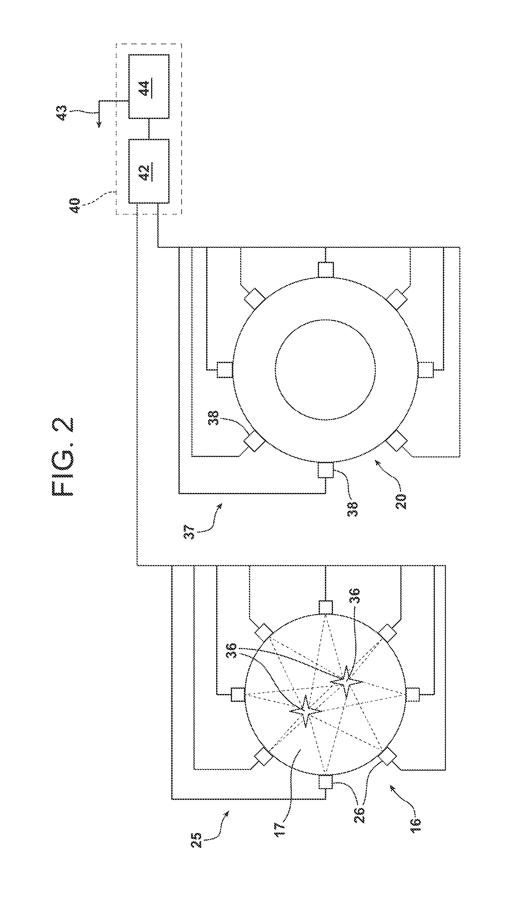
The invention provides a method and system for determining the temperature of a working gas passing through a duct in a gas turbine engine. The method involves identifying acoustic frequencies generated within the gas and determining the temperature value of the gas at a first location in the engine using a function and a calculated constant value. The system includes an acoustic sensor on the duct and a processor to determine the temperature value based on the frequency signals from the sensor. The method and system can be used to improve engine performance and control.

Problems solved by technology

For example, a controller may monitor a measured turbine exhaust temperature, and a measured change in temperature at the exhaust may result in the controller changing an operating condition of the engine.

Method used


Image

  • Temperature measurement in a gas turbine engine combustor
  • Temperature measurement in a gas turbine engine combustor
  • Temperature measurement in a gas turbine engine combustor

Examples


Embodiment Construction

[0048]In the following detailed description of the preferred embodiment, reference is made to the accompanying drawings that form a part hereof, and in which is shown by way of illustration, and not by way of limitation, a specific preferred embodiment in which the invention may be practiced. It is to be understood that other embodiments may be utilized and that changes may be made without departing from the spirit and scope of the present invention.

[0049]According to various aspects of the present invention, systems and methods are provided for determining a hot working gas temperature within a gas turbine engine using one or more detected acoustic frequencies from a passage for the working gas. For example, as will be described in greater detail herein, an acoustic frequency resulting from a combustion event, comprising combustion of a fuel / air mixture at a location within a passage to a turbine section of a gas turbine engine, is detected for determining the temperature within th...


PUM


Abstract

A method and system for determining a temperature of a working gas passing through a passage to a turbine section of a gas turbine engine. The method includes identifying an acoustic frequency at a first location in the engine upstream from the turbine section, and using the acoustic frequency for determining a first temperature value at the first location that is directly proportional to the acoustic frequency and a calculated constant value. A second temperature of the working gas is determined at a second location in the engine and, using the second temperature, a back calculation is performed to determine a temperature value for the working gas at the first location. The first temperature value is compared to the back calculated temperature value to change the calculated constant value to a recalculated constant value. Subsequent first temperature values at the first location may be determined based on the recalculated constant value.

Description

STATEMENT REGARDING FEDERALLY SPONSORED DEVELOPMENT[0001]Development for this invention was supported in part by Contract No. DE-FC26-05NT42644, awarded by the United States Department of Energy. Accordingly, the United States Government may have certain rights in this invention.FIELD OF THE INVENTION[0002]The present invention relates to temperature measurement in turbine engines and, more particularly, to determination of temperature of hot working gases entering a turbine section of an engine based on detection of a frequency signal produced within the working gases.BACKGROUND OF THE INVENTION[0003]Combustion turbines, such as gas turbine engines, generally comprise a compressor section, a combustor section, a turbine section and an exhaust section. In operation, the compressor section inducts and compresses ambient air. The combustor section generally may include a plurality of combustors for receiving the compressed air and mixing it with fuel to form a fuel / air mixture. The fu...

Claims


Application Information

Patent Timeline
IPC IPC(8): G01K11/22
CPCG01K11/22G01K11/26G01K2205/00G01K2013/024G01K13/02G01K15/005G01K2213/00G01K13/024
Inventor DESILVA, UPUL
Owner SIEMENS ENERGY INC
Learn More