
Smart glass slide for microarrays

Active Publication Date: 2014-09-18
ROBERT BOSCH GMBH
View PDF16 Cites 23 Cited by
  • Summary
  • Abstract
  • Description
  • Claims
  • Application Information

AI Technical Summary

Benefits of technology

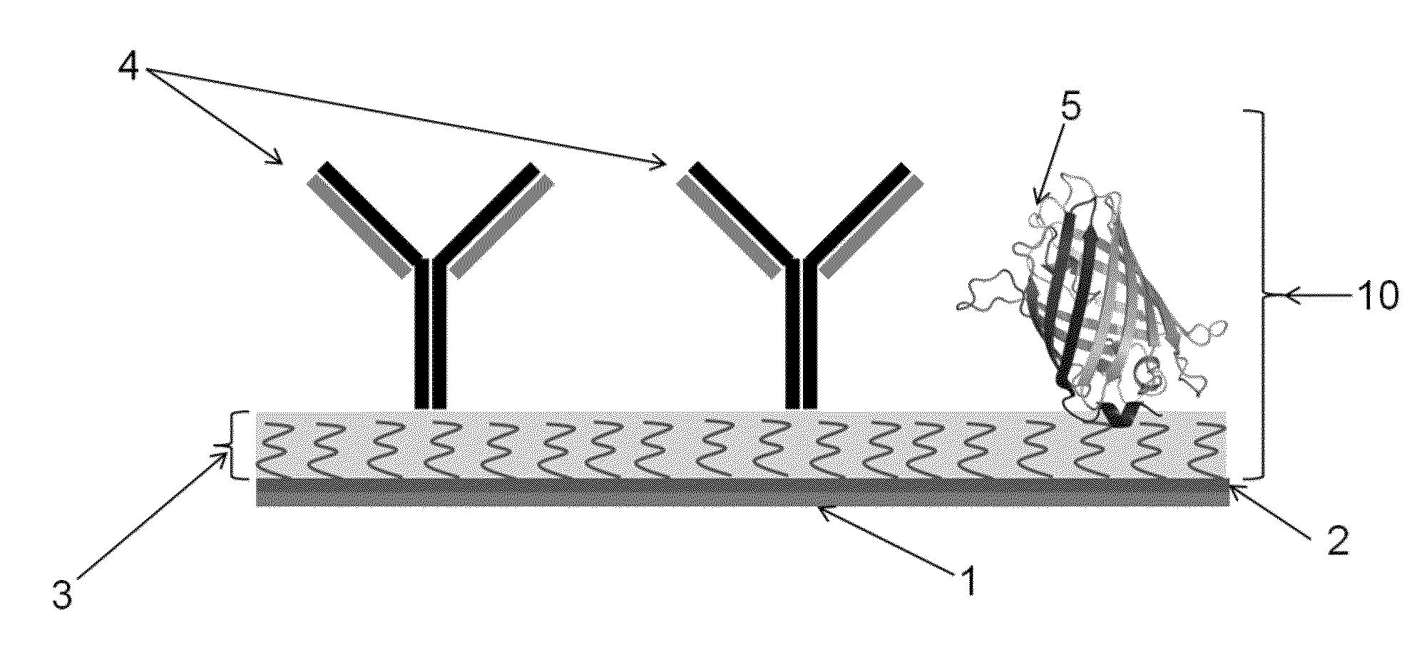
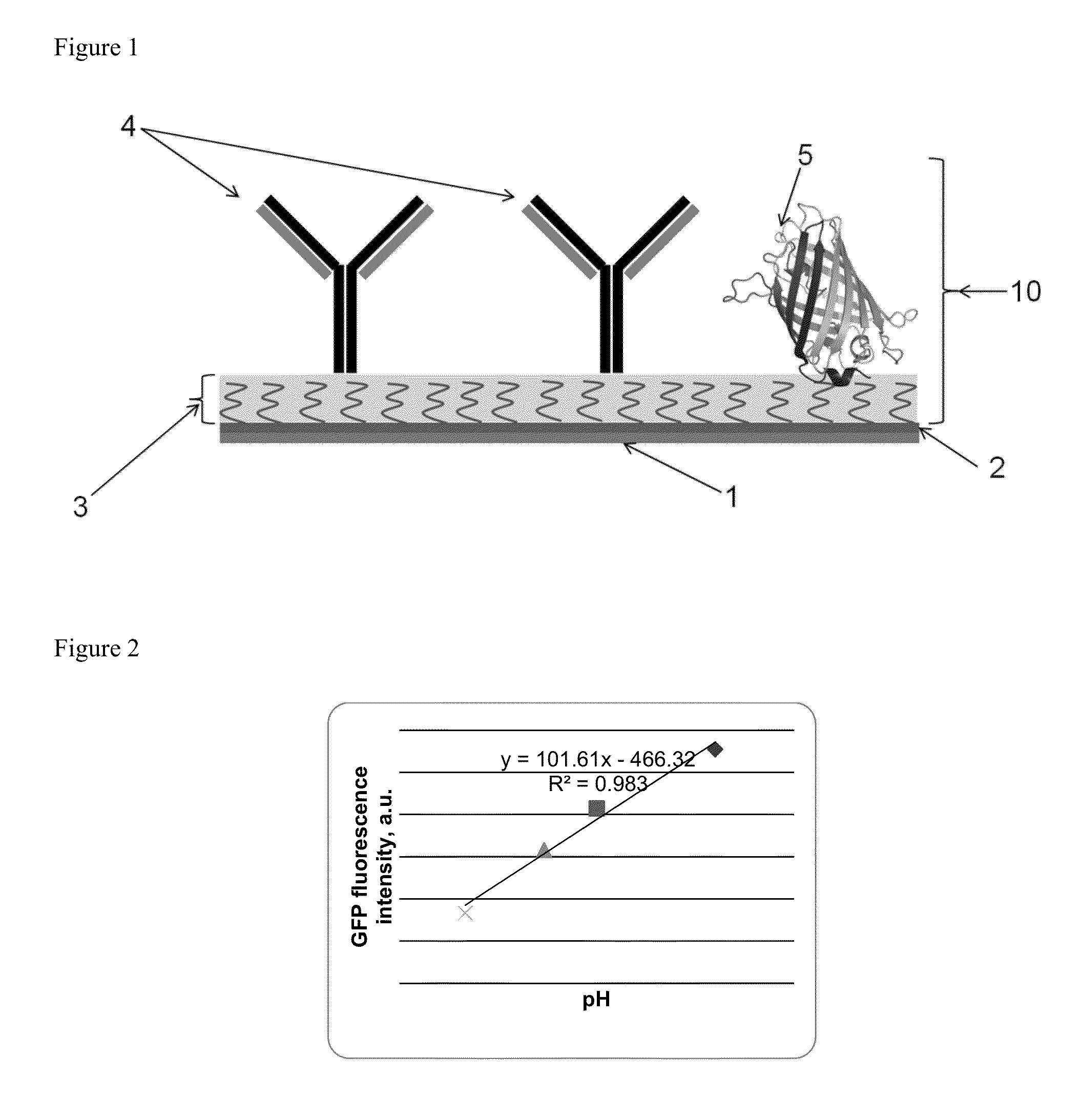
The patent text describes a device and method for controlling the pH in a biosensor with multiple test sites. This device can be integrated into a CMOS, electrode array, or TFT based biosensor and can be used to modulate the interactions between a probe biomolecule and a biomolecular analyte of interest. The device consists of a transparent support substrate with immobilized pH sensitive Fluorescent Protein and probes on its surface. By reacting an electrochemically active agent in an aqueous solution at each test site, the pH can be independently controlled. This allows for the detection of biomolecule analytes in a biological sample while maintaining accuracy and reliability. The technical effect of this device is to provide a tool for researchers to easily and accurately control the pH and ionic concentration in a biosensor, which can help to improve the accuracy and reliability of biomolecule analysis.

Problems solved by technology

Achieving the sensitivity and specificity needed in such tests is not without difficult challenges.
The two main limitations in a detection assay include sensitivity and cross-reactivity.
Both of these factors affect the minimum detectable concentration and therefore the diagnostic error rate.
The sensitivity in such tests is generally limited by label detection accuracy, association factor of the probe-analyte pair (for example an antibody-antigen pair), and the effective density of probe molecule (for example probe antibody) on the surface.
Solving the cross-reactivity and background problem can take a significant amount of time in the assay development of a new test and increases the cost and complexity of the overall test.
This results in a long development time, the infeasibility of tests in some cases, and a higher manufacturing cost.
Cross-reactivity of the proteins may be the source of the failure of such an effort.
Variations in the modulation of the local pH due to repeated use of the biosensor and variations between subsequent measurements may decrease the accuracy of the determination of the biomolecular analyte of interest by such biosensor.

Method used


Image

  • Smart glass slide for microarrays
  • Smart glass slide for microarrays
  • Smart glass slide for microarrays

Examples


examples

Electrochemical Modulation of pH as Monitored by Fluorescence Intensity with Green Fluorescence Protein (GFP)

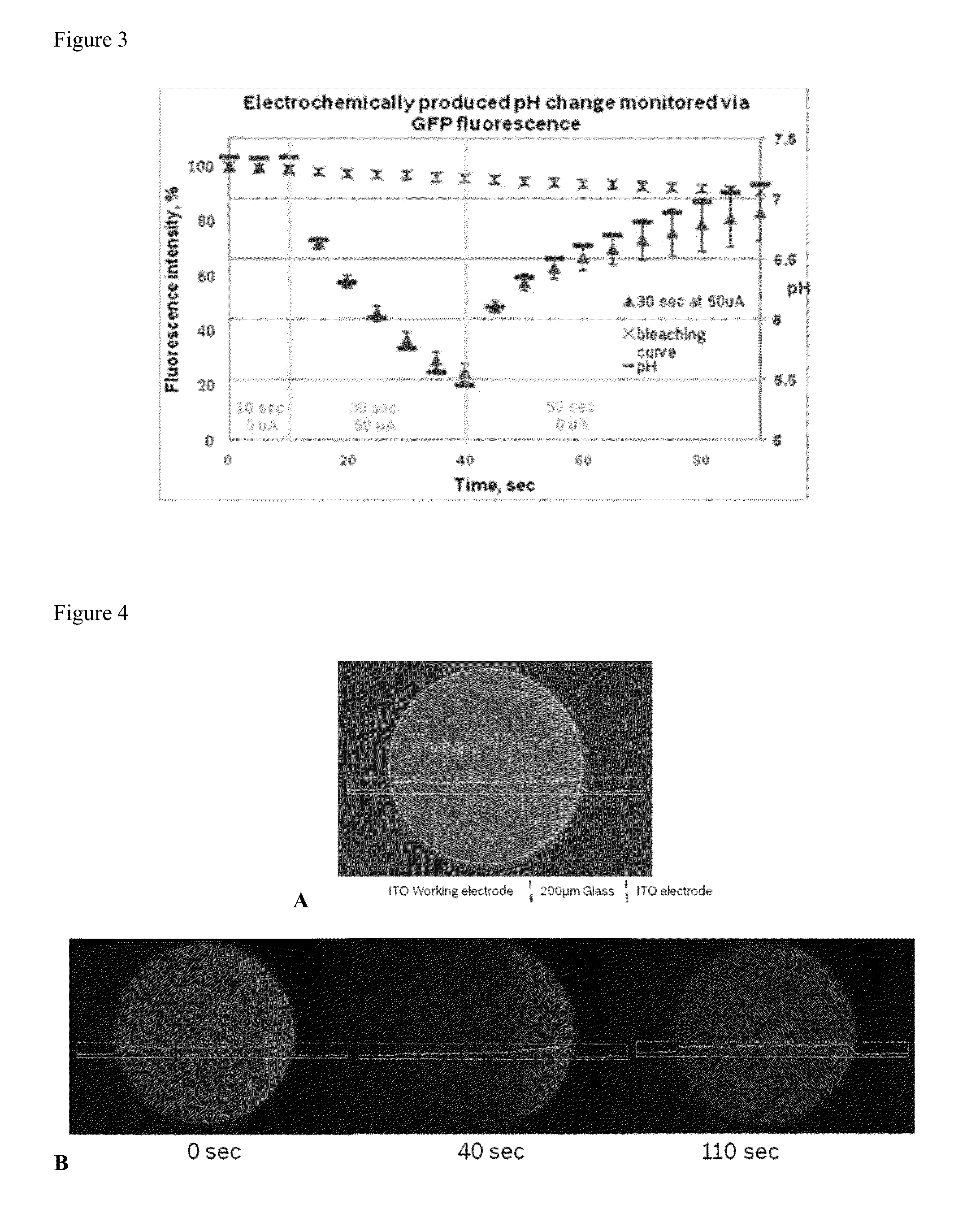
[0056]Electrode material used: The electrode material was indium tin oxide. The fluorescent protein used is GFP immobilized on a glass substrate which includes an array of electrodes. The GFP is applied as spots, each spot covers an area that overlaps with one electrode and an area that is not overlapping with an electrode.

[0057]The pH change at the surface of ITO working electrode is generated via current-driven oxidation of a redox active molecule, 2-methyl-1,4-dihydroquinone, in diluted phosphate buffer (pH=7.4) containing 0.1M Na2SO4. After 10 seconds of induction, current (50 microamps) was applied for 30 second, which resulted in a drop of solution pH to 5.5, as was observed by a change in GFP fluorescence intensity. FIG. 2 is used as calibration curve to assess the pH values. After current was turned off, the pH recovered to neutral value within 50 seconds (as shown in...


PUM


Abstract

Device for use in a biosensor comprising a multisite array of test sites, the device being useful for modulating the binding interactions between a (biomolecular) probe or detection agent and an analyte of interest from a biological by modulating the pH or ionic gradient near the electrodes in such biosensor. The device provides a biosensor which is more accurate, reliable and the results of which are more reproducible. Analytic methods for more accurately measuring an analyte of interest in a biological sample are also provided.

Description

FIELD OF THE INVENTION[0001]The invention relates to a device for use in microarrays in a biosensor and diagnostic methods for biomolecules using such biosensor comprising the device. Moreover, the invention relates to a method for accurately and reliably controlling a pH gradient near electrode surfaces for modulating biomolecular interactions in such biosensor.BACKGROUND INFORMATION[0002]Recently there has been an increased interest in predictive, preventative, and particularly personalized medicine which requires diagnostic tests with higher fidelity, e.g., sensitivity and specificity. Multiplexed measurement platforms, e.g., protein arrays currently used in research, are among the promising diagnostics technologies for the near future. The samples in these tests can be human body fluids such as blood, serum, saliva, biological cells, urine, or other biomolecules but can also be consumables such as milk, baby food, or water. Within this field there is a growing need for low-cost,...

Claims


Application Information

Patent Timeline
IPC IPC(8): G01N33/543
CPCG01N33/5438G01N27/3272
Inventor FOMINA, NADEZDAJOHNSON, CHRISTOPHERKAVUSI, SAMAHMAD, HABIB
Owner ROBERT BOSCH GMBH
Learn More