
Grayscale lithography of photo definable glass

a lithography and glass technology, applied in the field of three-dimensional microstructures, can solve the problems of increased autofluorescence, undesirable opaque portions, and exposed portions that are transformed into opaque ceramic materials, and achieve the effect of increasing autofluorescen

Inactive Publication Date: 2014-09-18
PHOTRONICS INC
View PDF2 Cites 22 Cited by
  • Summary
  • Abstract
  • Description
  • Claims
  • Application Information

AI Technical Summary

Benefits of technology

This patent describes a problem with current methods of creating three-dimensional microstructures in photosensitive glass substrates. The exposed portions are transformed into opaque ceramic material, which interferes with detection of fluorescent signals and is undesirable in some applications. The patent aims to solve this problem by introducing a new method that minimizes the formation of opaque ceramic material.

Problems solved by technology

A problem associated with the conventional method of forming a three-dimensional structure in photosensitive glass substrates is that the exposed portions are transformed into opaque ceramic material through the thickness of the substrate.
Particularly in the case of microfluidic applications, these opaque portions are undesirable.
Another problem associated with the conventional method is that the remaining ceramic portions will result in increased autofluorescence, which interferes with detection of fluorescent signals.

Method used


Image

  • Grayscale lithography of photo definable glass
  • Grayscale lithography of photo definable glass
  • Grayscale lithography of photo definable glass

Examples


Embodiment Construction

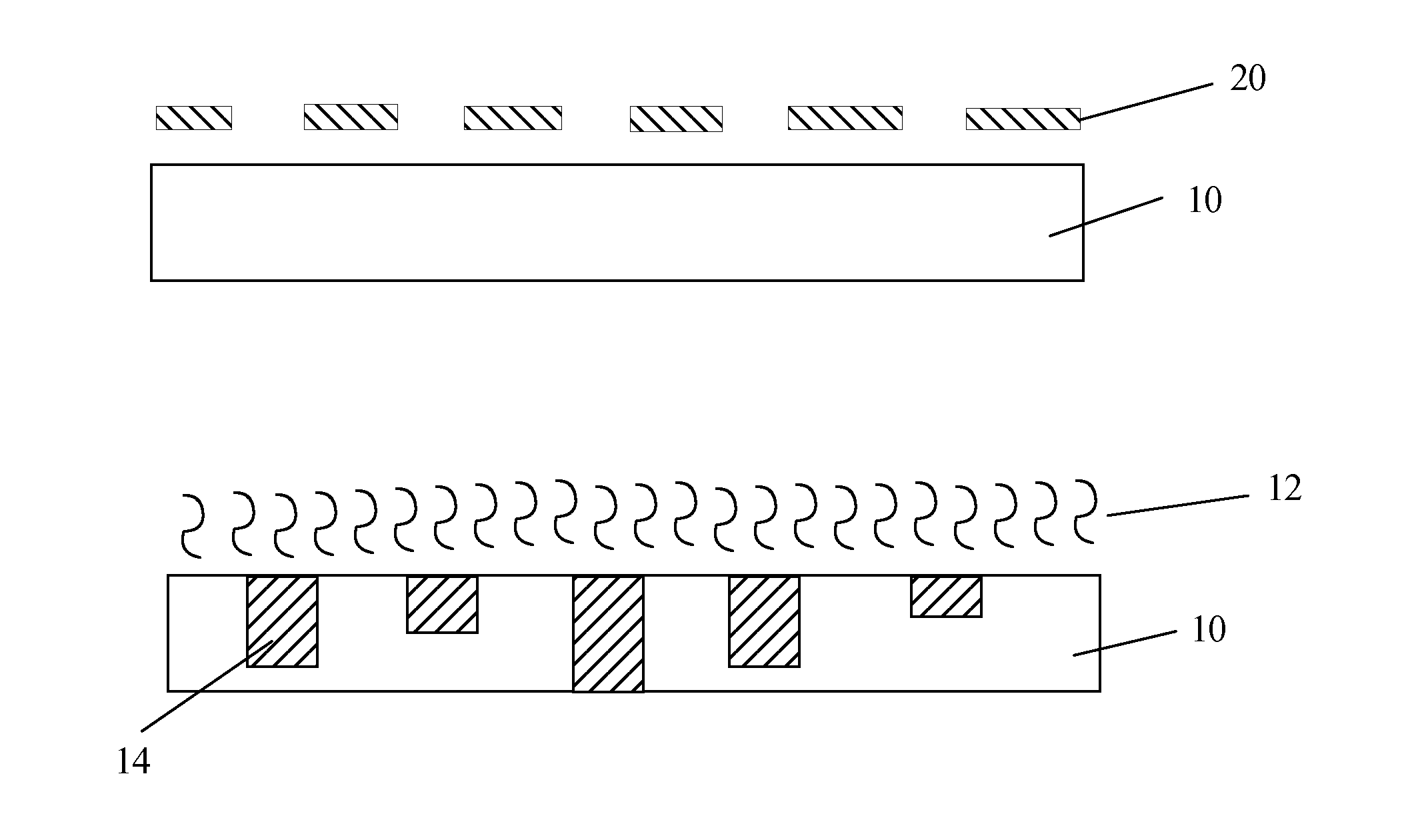
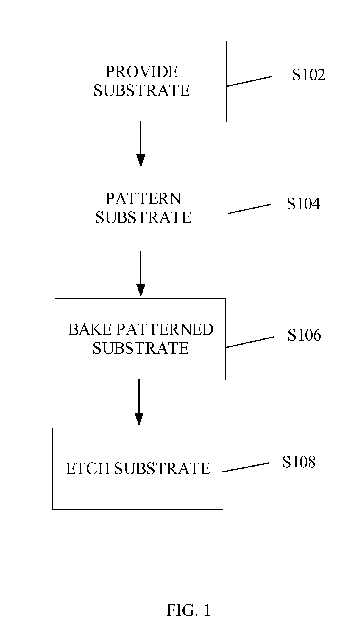
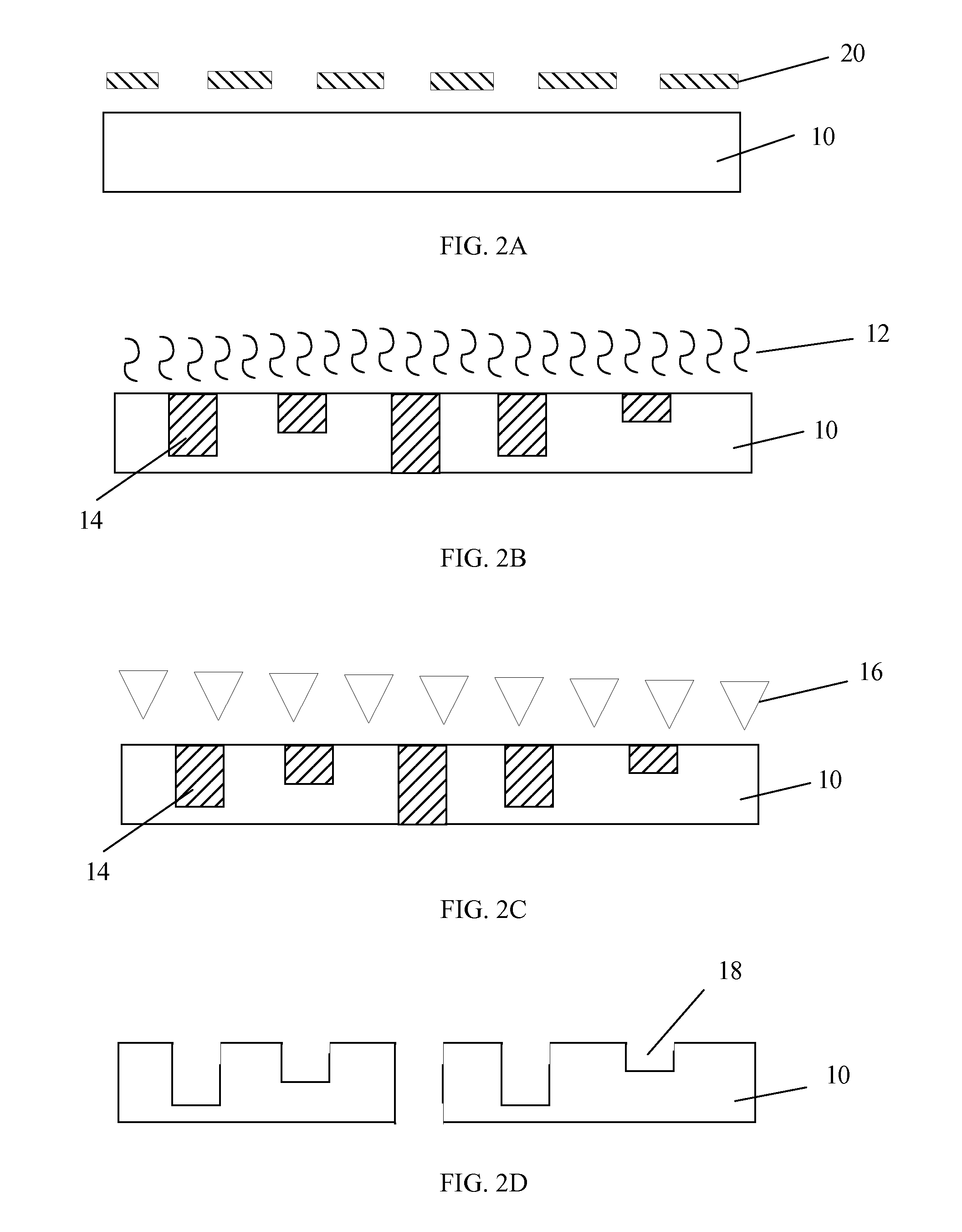
[0008]Various exemplary embodiments of the present invention are directed to a method of forming three-dimensional structures in a photosensitive glass substrate. In particular, according to exemplary embodiments, grayscale lithography techniques are used to partially expose portions of the photosensitive glass substrate to UV light so as to control the amount of substrate that is converted to ceramic material as a result of the exposure. The use of grayscale lithography allows for the formation of through-glass vias (TGVs) where ceramic through-conversion is full (100%), as well as the formation of other areas where the ceramic conversion is less than 100% (e.g., 0%, 10%, 20%, 50%, etc.). Thus, microfluidic and other types of three-dimensional microstructures can be formed with, for example, TGVs, channels and sub-features within the channels, with a single exposure.

[0009]According to exemplary embodiments of the present invention, any suitable grayscale lithography technique may b...


PUM

PropertyMeasurementUnit
temperatureaaaaaaaaaa
thicknessaaaaaaaaaa
thicknessaaaaaaaaaa

Abstract

A method for forming a three-dimensional microstructure includes providing a photosensitive glass substrate; exposing the photosensitive glass substrate to energy through a continuous tone, variable transmission photomask so as to form opaque portions in the photosensitive glass substrate, each of the opaque portions having one of a variety of depths extending through the entire thickness of the photosensitive glass substrate; and removing the opaque portions so as to form three-dimensional features in the photosensitive glass substrate.

Description

FIELD OF THE INVENTION[0001]The present invention relates to three-dimensional microstructures and methods of manufacturing three-dimensional microstructures.SUMMARY OF THE INVENTION[0002]Conventional optical lithography techniques used for fabricating integrated circuits have been adapted to manufacture three-dimensional microstructures, such as microarrays, microfluidic devices, titer plates, microelectromechanical systems (MEMS) and three-dimensional glass structures. In conventional optical lithography, a fully resolved pattern is etched into a binary photomask and transferred to a wafer by exposing the wafer through an exposure tool (e.g., stepper). More particularly, binary photomasks are typically comprised of a substantially transparent substrate (e.g., quartz) and an opaque layer (e.g., chrome) in which the pattern to be transferred is etched. It is also known that other layers may be included on the photomask, including, for example, an antireflective layer (e.g., chrome o...

Claims


Application Information

Patent Timeline
Patent Type & Authority Applications(United States)
IPC IPC(8): G03F7/20
CPCG03F7/20G03F7/0043G03F1/50Y02E50/17Y02E50/10
Inventor DILLION, BRIAN W.
Owner PHOTRONICS INC
Learn More